About submarine cables
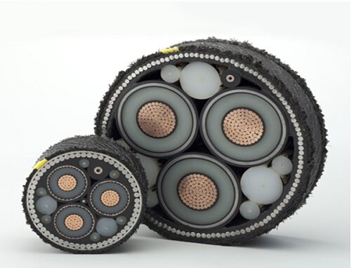
Figure 1 - cross section of a 3-phase submarine cable
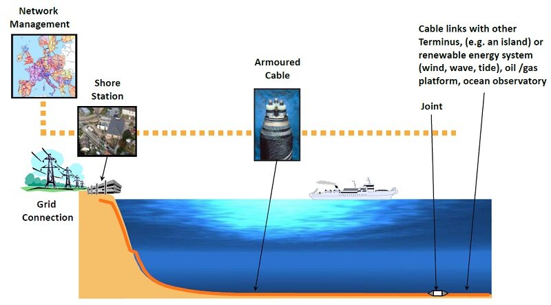
Figure 2 - Typical submarine power cable system
Which is better - AC or DC power transmission?
Most power systems utilize alternating current (AC) due to its ease of voltage manipulation with transformers. Stepping up AC voltage reduces line current, minimizing resistive losses. However, direct current (DC) transmission is gaining traction due to its advantages. DC lines can carry over 1.4 times more power than AC lines of the same size, as they are not limited by the RMS voltage. DC transmission eliminates reactive losses present in AC lines, making it more efficient over long distances. While AC requires expensive equipment, DC becomes economically advantageous, especially for underwater transmission systems, despite most submarine cables still employing AC.
AC subsea cables
AC submarine cables facilitate the transmission of three-phase electric power. For lower power needs, three-core cables consolidate conductors in one underwater cable, typical in offshore wind farms. Larger power transmissions employ three separate single-core cables, often with a fourth cable as a spare. This redundancy ensures rapid replacement in case of damage, such as from ship anchors. Table 1 outlines examples of installed AC submarine cables, underscoring their pivotal role in underwater power transmission.
| Connecting | Connecting | Voltage |
| Tarifa, Spain (Spain-Morocco Interconnection) | Fardioua, Morocco through the Strait of Gibraltar | 400 kV |
| Mainland Sweden | Bornholm Island, Denmark | 60 kV |
| Wolfe Island, Canada | Kingston, Canada | 245 kV |
Table 1 - Examples of AC submarine cables
Applications
- Historically, submarine power cables linked shore-based power grids across bays, estuaries, rivers, straits, etc.
- Now submarine cables carry power between countries and to offshore installations, e.g. oil/gas platforms and ocean science observatories.
- Submarine cables also transfer power from offshore renewable energy schemes to shore, e.g. wind, wave and tidal systems.
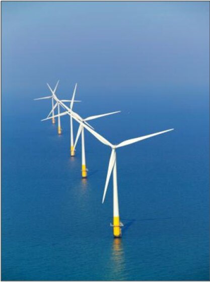
Figure 3 - Offshore wind farm in UK
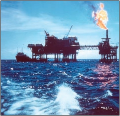
Figure 4 - Offshore oil platform with power supply through a submarine cable
Power cables EM radiation and environment
Operational AC transmission subsea cables generate electromagnetic fields, with electric fields intensifying with voltage and magnetic fields with current flow. Effective cable design, like three-phase AC systems, can mitigate magnetic field strengths exceeding terrestrial levels. While direct electric fields can be managed with shielding, induced electric fields persist. Burial reduces field exposure, crucial for marine species sensitive to electromagnetic fields. Studies show cable-induced fields may disrupt fish and marine mammal orientation and migration. Sensitivity varies among species; for instance, elasmobranchs are highly electrosensitive. Engineers must consider marine life sensitivity in subsea cable design and construction.
Electromagnetic simulation of three phase submarine cable
Numerical simulation aids in understanding and designing submarine cables, ensuring compliance with environmental electromagnetic (EM) field regulations. EMS facilitates cable design and analysis, particularly with its AC Electric solver. This tool computes key parameters like Electric Field (V/m), Current Density (Amps/m²), and Resistance (Ohms), enabling engineers to model and assess cable behavior efficiently. This article focuses on the AC Electric study, demonstrating its effectiveness in simulating electric field dynamics within submarine cables, crucial for optimizing design and mitigating environmental impact.
Simulation
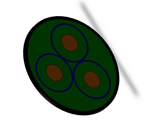
Figure 5 - 3D model of the 3 phase submarine cable
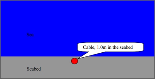
Figure 6 - Cabling scenario of the subsea cable used in simulation
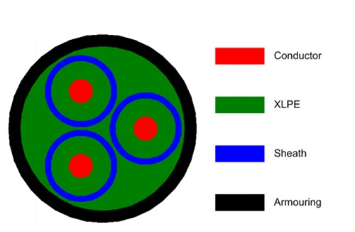
Figure 7 - Geometrical model of the submarine cable for simulation
Operating at 50 Hz with 135kV AC voltage between phases, the cable's behavior is analyzed using the AC Electric solver, which generates current distributions, E-field distributions, and potential differences. Figure 8 illustrates the electric field distribution within all cable cores. With metallic sheaths creating earthed shields for all cores, the E-fields are confined within each core, displaying a radially symmetric distribution within the dielectric XLPE. Consequently, no E-field leaks from each core, resulting in no E-field outside the submarine cable. The electric field reaches its maximum value at the conductor's surface, approximately 1.0969 x 10^7 V/m.
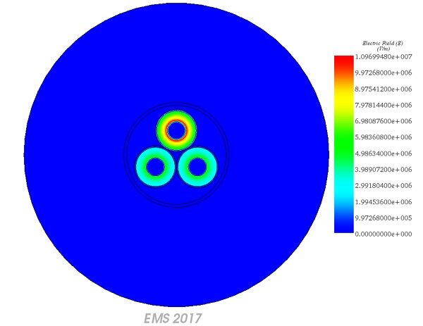
Figure 8 - E field distribution