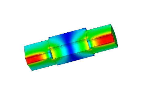
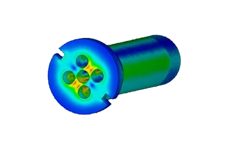
Optimizing Waveguide-to-Coax Adapters for 2.4 GHz Applications
Waveguide to Coax Adapter
Coaxial cables, known for their multi-layered structure, and waveguides, which guide various types of waves, serve crucial roles in electrical engineering. Waveguides of specific dimensions enable the propagation of electromagnetic waves at precise frequencies and find applications even in integrated circuits. Waveguide-to-coaxial adapters bridge these technologies, consisting of components like waveguide fittings, flanges, and coaxial probe assemblies. In this example, we demonstrate the design of a 2.4 GHz rectangular waveguide-to-coaxial transition using HFWorks.
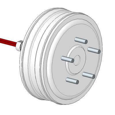
Figure 1 - Geometry of the coaxial antenna
Waveguides serve as high-pass filters with a cutoff frequency dictated by the dispersion relation on wavenumber (k). The simulation confirms this, rejecting frequencies below a specific threshold.
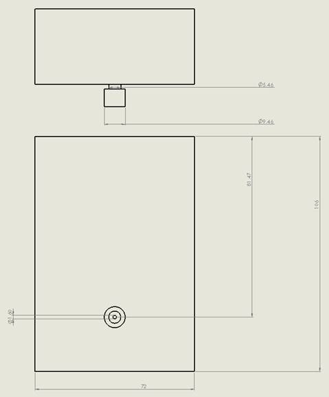
The adapter's design results from conceptualizing and optimizing a set of dimension variables illustrated in the figure below:
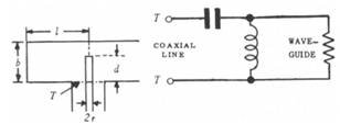
Figure 2 - The simple transition
Simulation
This simulation allows us to analyze the properties of the modeled coaxial cable to waveguide transition, including power loss, return loss, and near-field plots in both the E and H planes. Additionally, it enables us to visualize the animated transition in 3D as electromagnetic waves propagate within the waveguide's hollow.
Load/ Restraint
In this simulation, the waveguide features a cavity with air surrounding the coaxial conductor's stem, and the input port is located at the bottom of this cavity. A second port is assigned to the open face of the waveguide. In our analysis, we consider both the conductors and the conductive walls of the waveguide as Perfect Electric Conductors (PEC).
Results
The Smith Chart provides a visualization of the return loss of the connection between the coaxial support and the waveguide over a frequency range from 2 to 4 GHz. To obtain a smoother curve, you can apply a smaller frequency step, which helps refine the details of the return loss behavior over the frequency band.
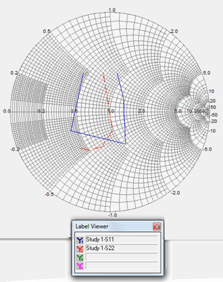
Figure 3 - Transition's return loss at both ports
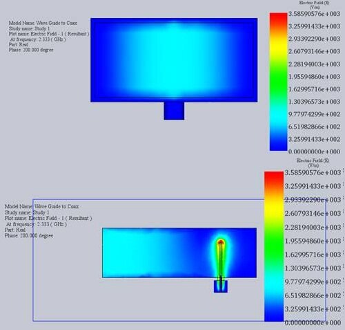
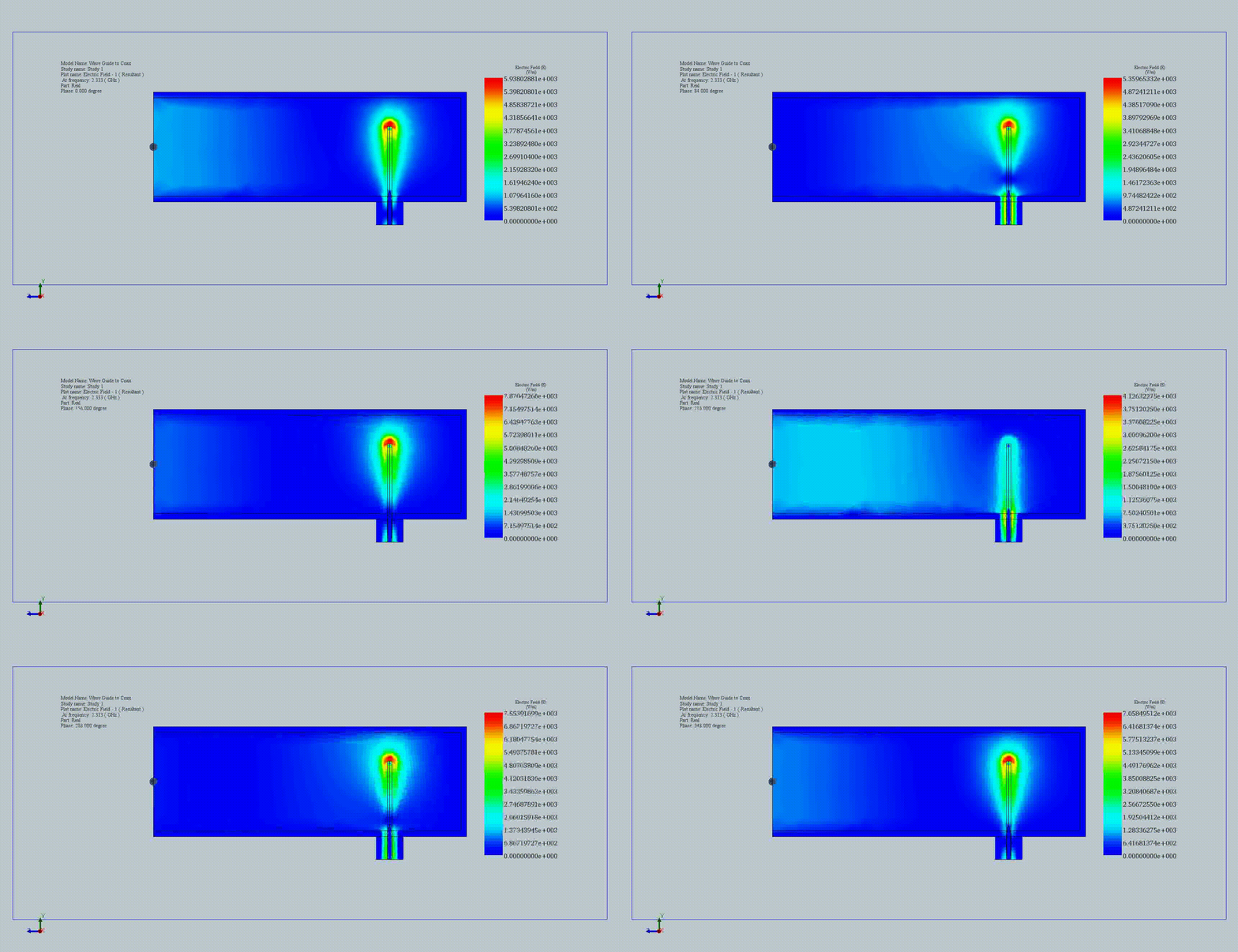
Figure 4 - Wave propagation in the antenna at 2.33 GHz (Front and right views)
These captures provide insight into the near distribution of the electric field within the waveguide-to-coax adapter. The second view, which involves surface clipping, is a feature available in HFWorks that allows for the exploration of the distribution of E (electric field) and H (magnetic field) within the inner parts of the structure. This feature enables a more detailed analysis of the electromagnetic fields within the adapter.
Conclusion
This application note showcases the design and simulation of a 2.4 GHz rectangular waveguide-to-coaxial adapter using HFWorks, bridging the functionalities of coaxial cables and waveguides in electrical engineering. Waveguides, acting as high-pass filters, facilitate the propagation of electromagnetic waves within specific frequency ranges, while coaxial cables offer versatile connectivity options. The adapter combines these elements to ensure seamless transmission of signals across different media. Through meticulous simulation, key performance metrics such as power loss, return loss, and the distribution of electromagnetic fields in both E and H planes are examined, providing valuable insights into the adapter's efficiency and effectiveness. The use of Perfect Electric Conductors (PEC) for both the waveguide walls and the coaxial conductor ensures accurate modeling of electromagnetic behavior. The Smith Chart and detailed near-field plots further elucidate the return loss characteristics and wave propagation dynamics, underscoring the adapter's capability to maintain signal integrity and optimize connectivity between coaxial and waveguide systems.


