Effect of Skew Angle and Airgap on Torque Ripple with EMWORKS-MotorWizard
Introduction
This application note investigates the effects of skew angle and airgap variations on torque ripple in permanent magnet synchronous motors (PMSMs). Using EMWORKS-MotorWizard for simulation, this study provides insights into optimizing motor performance. PMSMs are widely recognized for their high-power density, efficiency, and reliable performance, but they also face challenges such as high system costs, potential demagnetization, and complex control requirements.
Design Process Using MotorWizard
The design of PMSMs involves a structured process to achieve optimal performance:
-
Define the number of poles, slots, and winding configuration.
-
Select materials and estimate the main dimensions of the motor.
-
Set the airgap length, design the rotor structure, and determine magnet size.
-
Calculate the number of turns and optimize the conductor's size.
-
Specify stator slot type and dimensions.
-
Determine stator and rotor yoke thickness.
-
Conduct comprehensive design analysis.
One critical parameter in the design process is the definition of the airgap, as it significantly influences the back EMF value and profile and affects both cogging torque and torque ripple. To thoroughly analyze and detail the electromagnetic performance, we will utilize the MotorWizard-based template software.
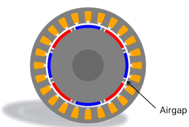
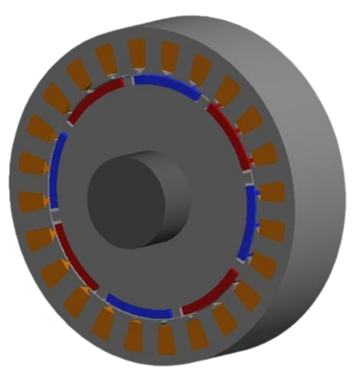
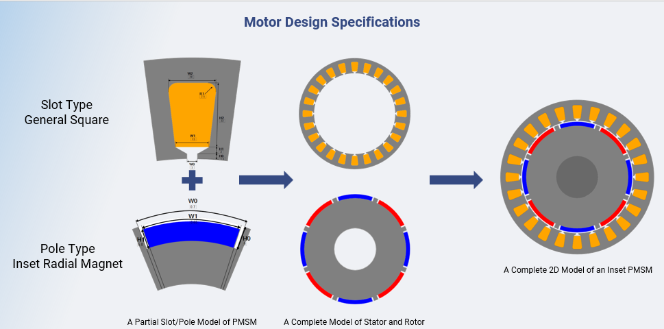
2D View of an Inset PMSM using MotorWizard
Motor design specifications
| Input parameters | Values |
| Rated RMS Current (A) | 30 |
| Rated RMS Voltage (V) | 220 |
| Maximum Speed (rpm) | 7500 |
| Rated Power (W) | 1500 |
| Operating Temperature (C) | 75 |
| Number of Slots | 24 |
| Number of Poles | 8 |
| Model Length | 30 |
EMOWRKS-MotorWizard offers users a variety of slot and pole templates to select from. Its flexible editor viewer window allows users to define geometric inputs for one section easily and directly, providing a quick overview of the entire configuration. In this study, we are working with general square slot and inset radial magnet topology.
Torque vs. Speed and Efficiency Map Analysis
Analyzing the torque versus speed and efficiency map is essential for evaluating motor performance. The airgap length significantly influences these parameters. In the following study we will consider three airgap dimensions as shown here:

Insert PMSM with 1 mm Airgap Insert PMSM with 2 mm Airgap Insert PMSM with 3 mm Airgap
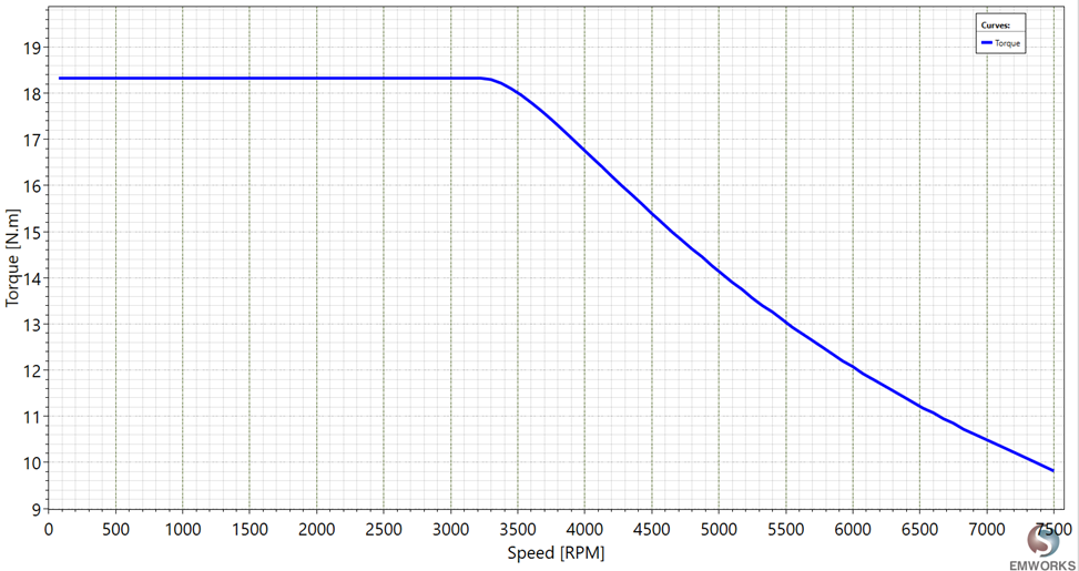
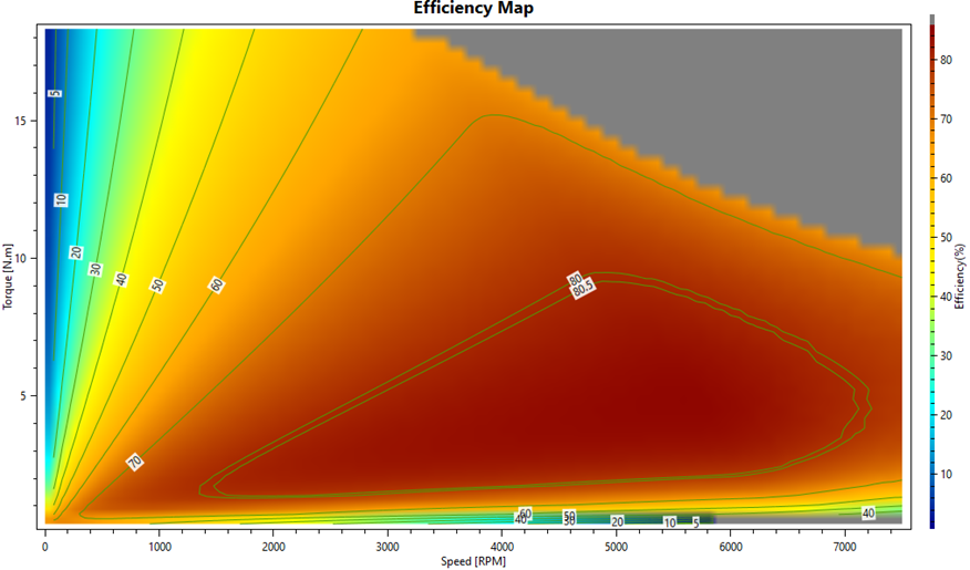
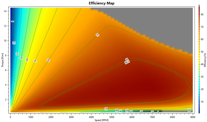
Torque vs. Speed Plot of an Inset PMSM with 1 mm Airgap Efficiency Map of an Inset PMSM with 1 mm Airgap
The 1 mm airgap design demonstrates the highest torque and efficiency, making it ideal for applications that require high starting torque. However, the small airgap presents manufacturing challenges.
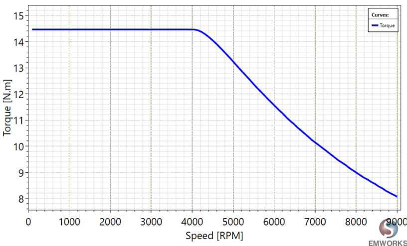
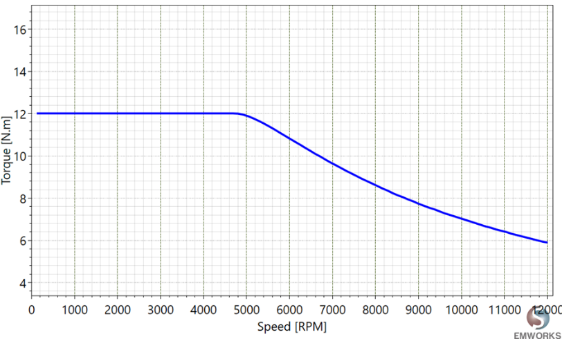
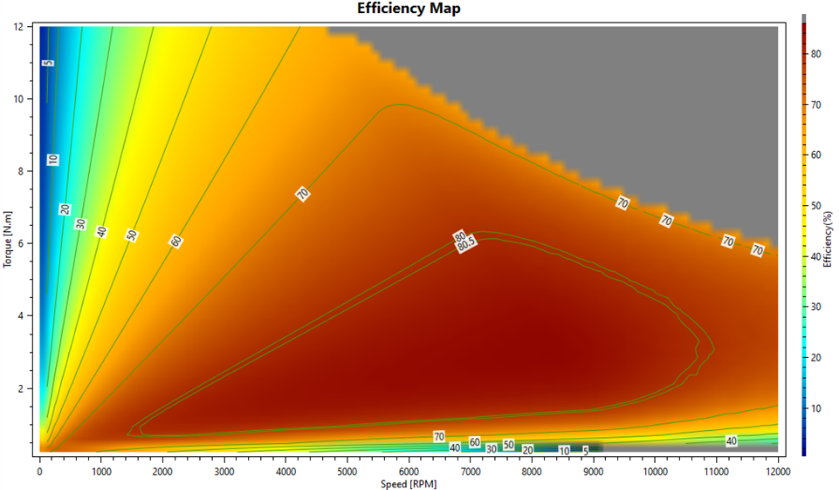
Torque vs. Speed Plot of an Inset PMSM with 2 mm Airgap Efficiency Map of an Inset PMSM with 2 mm Airgap
The second configuration presents a balanced perspective for the motor performance. It provides adequate torque for most applications and delivers better tolerance for manufacturing process.
Torque vs. Speed Plot of an Inset PMSM with 3 mm Airgap Efficiency Map of an Inset PMSM with 3 mm Airgap
For the third topology the torque and the efficiency are reducing that is explained by the increase of the magnetic reactance and the flux leakage. However, the larger airgap provides more mechanical stability.
Flux Linkage
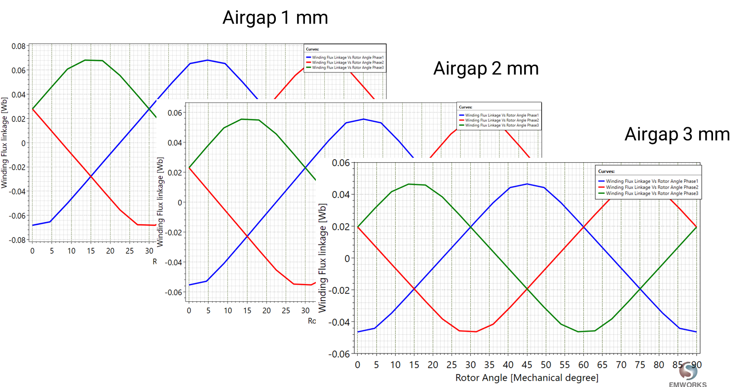
The three phase magnetic flux linkage are also evaluated for the proposed topologies.
| Peak Flux Linkage phase A (wb) | |
| Airgap 1 mm | 0.068 |
| Airgap 2 mm | 0.055 |
| Airgap 3 mm | 0.046 |
A smaller airgap results in improved flux linkage, which significantly boosts torque and overall motor efficiency. This is because a reduced airgap distance enhances the interaction between the stator and rotor, allowing more magnetic flux to contribute effectively to the torque production process. Consequently, the closer proximity of the components facilitates a more efficient transfer of energy, leading to better performance of the motor.
Back EMF
MotorWizard also computes the three-phase induced back EMF, which shows a similar trend to the flux linkage: a smaller airgap leads to higher induced voltage, while a larger airgap results in a decrease. Optimizing the airgap is crucial for enhancing motor performance, and it is equally important to manage heating, electrical, and mechanical stress to achieve a balanced and stable motor.
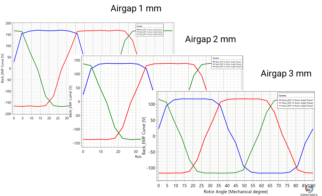
| Peak Back EMF phase A (V) | |
| Airgap 1 mm | 168.79 |
| Airgap 2 mm | 138.15 |
| Airgap 3 mm | 117.71 |
Cogging Torque
Cogging torque, an inherent characteristic of permanent magnet electric motors, can cause vibrations, noise, and instability during operation. These adverse effects compromise the smoothness and precision of the motor's performance, which is particularly detrimental in applications demanding high accuracy and consistency. Therefore, minimizing cogging torque is crucial to enhance motor efficiency, ensure quieter operation, and achieve greater stability and reliability in various mechanical and industrial applications.
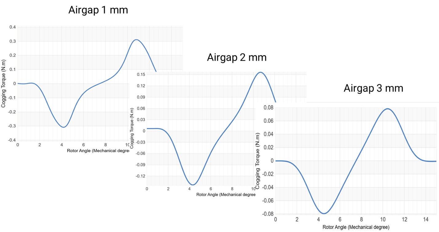
| Peak to Peak Cogging Torque (Nm) | |
| Airgap 1 mm | 0.620 |
| Airgap 2 mm | 0.300 |
| Airgap 3 mm | 0.157 |
The figure and the table demonstrate that as the airgap increases, the cogging torque minimizes and becomes smoother.
Electromagnetic Torque
In the first topology, which features a smaller airgap, the average torque is higher since most of the flux linkage contributes to generating electromagnetic torque. However, this configuration also exhibits higher torque ripples. Conversely, with a larger airgap, the average torque decreases due to increased leakage flux, but the torque becomes smoother.
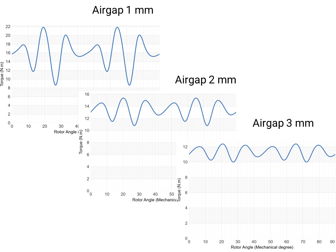
| Average Torque (Nm) | |
| Airgap 1 mm | 16.04 |
| Airgap 2 mm | 13.7 |
| Airgap 3 mm | 11.8 |
Skew Angle Adjustment
Skewing involves arranging the laminations of the rotor or stator at an angle to the motor axis, reducing cogging torque and torque ripple and resulting in smoother and quieter motor operation. Different skew techniques are defined in the literature such as linear skew-shaped skew, and zigzag skew. In our study, we will focus on linear skew where the rotor part is divided into 7 slices and each slice is shifted linearly along the motion axis. Consequently, we define the optimal skew angle as follows:
360/ LCM (24,8) = 15 deg
Three cases will be analyzed in the next steps to show the impact of the skew angle on the torque ripple reduction. For that we will consider:
- Case 1: Skewed angle 5 deg
- Case 2: Skewed angle 10 deg
- Case 3: Skewed angle 15 deg
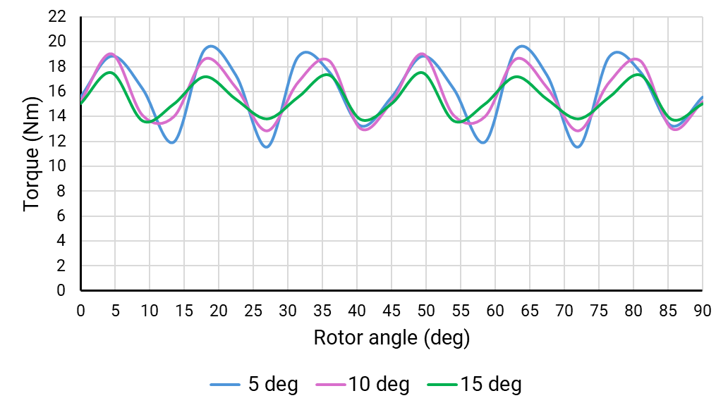
| Torque Ripple Comparison (%) | |
| Without Skewing | 76.78617 |
| With Skew Angle: 5 deg | 48.72102 |
| With Skew Angle: 10 deg | 39.25392 |
| With Skew Angle: 15 deg | 25.40038 |
Referring to the torque versus rotor angle plots and the table summarizing the torque ripple percentage, we can deduce that working with optimal skew angle which is equal to 15 degrees leads to smoother operation.
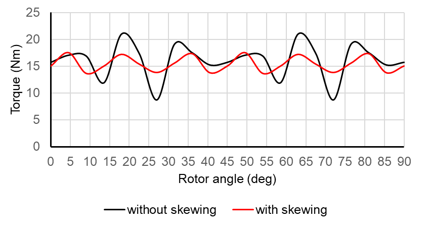
The figure underscores how skewing affects motor performance, highlighting how it can improve torque quality by minimizing harmonic content and reducing operational noise. Decreasing ripples by 50% expands the motor's suitability for applications requiring higher accuracy and sensitivity.
Conclusion
The simulation results clearly demonstrate that both airgap length and skew angle significantly affect PMSM performance. A smaller airgap increases efficiency and torque but also raises cogging torque and torque ripple. Skewing, particularly at the optimal angle of 15 degrees, effectively reduces torque ripple and enhances overall motor performance, albeit with added manufacturing complexity and cost. By optimizing these parameters, motor designers can achieve a balance between performance and manufacturability, leading to more efficient and reliable motor designs.


