Understanding Radome Effects on Antenna Efficiency
A Radome
A radome, a fusion of "radar" and "dome," serves as a protective shell for radar or microwave antennas. Composed of a material that minimizes signal interference, it acts as a transparent barrier to radar and radio waves. Radomes shield antennas from environmental factors like wind, rain, ice, and UV rays, and they can conceal electronic equipment. Furthermore, they enhance safety by preventing accidents caused by rapidly rotating antennas. In this analysis, we examine the complete structure, encompassing the radome, antenna, ground, and SMA connector.
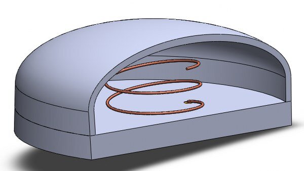
Figure 1 - Helical antenna model covered by a radome
Simulation
In this antenna simulation, a fine frequency step is employed within the frequency range of 2 GHz to 3 GHz to ensure precision. The dimensions of the antenna have been carefully optimized for efficient operation at 2.45 GHz.
Solids and Materials
The antenna structure follows the specifications of the helix antenna example available on the EMWorks website. The radome is seamlessly added to this structure using SolidWorks' "dome" feature, providing comprehensive protection for the antenna.
Load/ Restraint
The same radiation boundaries as the helix antenna example are applied to this simulation. Additionally, the radome is assigned the Duroid 5880 material, ensuring an accurate representation of its electromagnetic properties.
Result
Various 3D and 2D plots are available for analysis in this antenna simulation. One of the essential plots for an antenna is the radiation pattern, which illustrates how the antenna radiates electromagnetic waves in different directions. Below, you can see the radiation pattern of the analyzed antenna at 2.45 GHz:
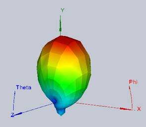
Figure 2 - 3D Radiation pattern of the antenna
The far-field radiation pattern of the antenna, covered by the radome, is depicted in the plot above at 2.45 GHz. To enhance the accuracy of this plot, we can reduce the steps for both Theta and Phi angles, resulting in smoother and more detailed results.
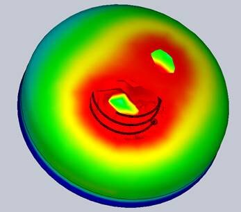
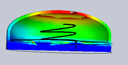
Figure 3 - 3D near field distribution of a dipole of the antenna at 2.45 GHz (Iso (left) and Section (right) Clipping)
In this figure, we observe the 3D near-field radiation of the antenna, and it is evident that the radome performs effectively at the desired frequency by allowing the electric field to pass through. This insight was obtained using the Iso Clipping feature of HFWorks. Additionally, we can explore the internal structure of the antenna by utilizing section clipping. The next figure illustrates the variations of the reflection coefficient at the antenna's port.
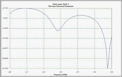
Figure 3 - Variations of reflection coefficient at the antenna's port
Conclusion
This application note delves into the design and simulation of a radome-protected helical antenna, focusing on its performance at the targeted frequency of 2.45 GHz. Radomes, combining the words "radar" and "dome," serve as protective enclosures that minimize signal interference while safeguarding antennas from environmental hazards and concealing electronic components. The simulation conducted within the 2 GHz to 3 GHz frequency range employs fine frequency steps to ensure precision, adhering to the specifications of a helix antenna and integrating a radome using SolidWorks. The radome's material, Duroid 5880, accurately represents its electromagnetic characteristics, maintaining the antenna's efficiency under protection. The results, highlighted through various 3D and 2D plots, showcase the antenna's far-field radiation pattern and near-field distribution at 2.45 GHz, affirming the radome's effectiveness in allowing electric field transmission without compromising the antenna's function. The analysis concludes that the radome not only provides essential protection but also maintains the antenna's operational integrity, thereby underscoring the importance of incorporating radomes in antenna designs for enhanced performance and safety.

