Impact of GSM/LTE/WLAN Antennas on Human Health
Exposure to GSM/LTE/WLAN Antenna
Mobile and smartphone antennas have rapidly evolved to meet the demands of advancing 3G, 4G, and 5G technologies. Concurrently, the health impacts of electromagnetic fields on humans have sparked significant research and debate regarding safety. This study focuses on analyzing the electromagnetic interaction between a printed mobile antenna, designed for GSM/LTE/WLAN applications, and human head tissue. The antenna in question operates across broad frequency bands, including LTE700/GSM850/GSM900 and GSM1800/1900/LTE2300/2500.
CAD Model
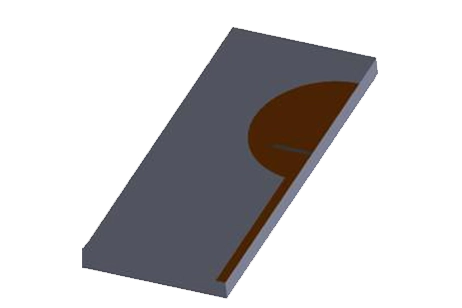
The geometry of the planar antenna, featuring a T-shaped coupling feed and an inductive shorting strip, is depicted in Figure 1. It is printed on a 1.6mm thick FR4 substrate, measuring 120mm in length and 36mm in width. The active part of the antenna, occupying a compact area of 36mm by 20mm, is located on the top ungrounded section of the circuit board, while the remainder serves as a ground plane, measuring 100mm by 36mm. The antenna connects through a 50-ohm coaxial cable.

Simulation Results
The HFWorks Antenna solver is utilized for the frequency range of 0.5 GHz to 3 GHz, with the FR4 material specified having a relative permittivity of 4.4 and a dielectric loss tangent factor of 0.02.
To ensure result accuracy, a mesh refinement strategy is applied to the port, conductor edges, and the slot side. Following the completion of the study, the simulation provided detailed outcomes.
Free Space Antenna Analysis
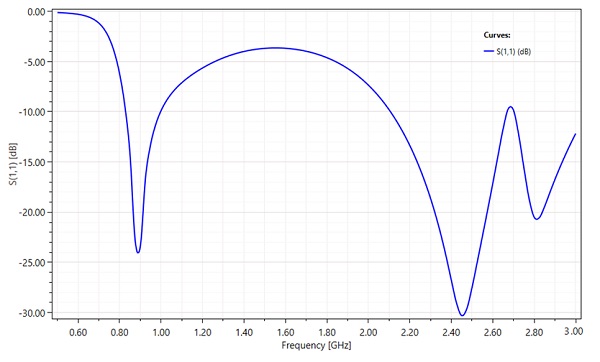
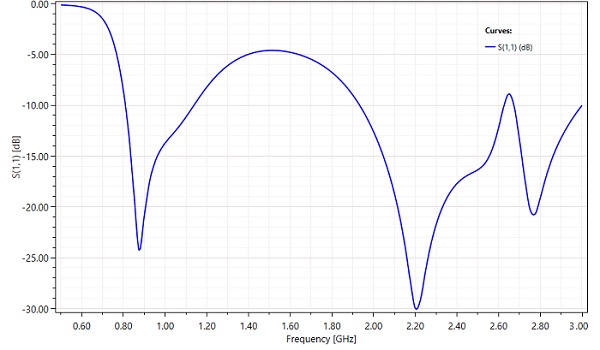
The initial segment of the study focuses on evaluating the antenna's performance in free space. Figure 2 displays the return loss results, clearly indicating that the antenna supports two distinct operating bands: a lower band with a bandwidth of 170 MHz (spanning 830 to 1000MHz) suitable for GSM850/GSM900 applications, and an upper band with a bandwidth of 570 MHz, encompassing LTE2300/LTE2500 and WLAN2400 applications.
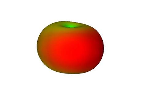
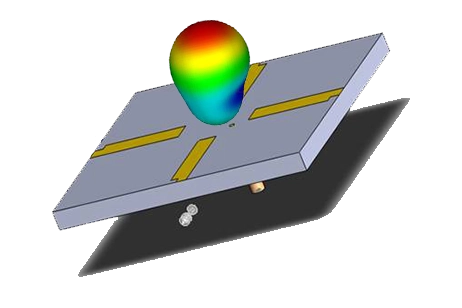
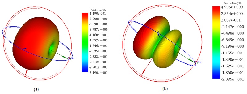
At 900 MHz, the antenna exhibits a good omnidirectional radiation pattern, confirming its stable radiation characteristics over the lower band compared to the higher frequency band.
Near Head Antenna Analysis
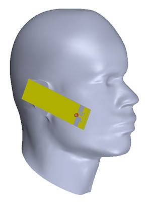
The second part of the study focuses on the core objective of the paper: analyzing the effect of the antenna's electromagnetic radiation on human head tissue. To this end, a human head phantom, positioned 5mm away from the antenna, is introduced. This phantom is constructed from a single equivalent material, with its properties detailed in Table 1.
| Material | Relative permittivity | Electrical conductivity (S/m) | Thermal conductivity (W/m. K) | Specific heat (J/Kg. K) | Mass density (Kg/ |
| Human head equivalent material | 42.61 | 1.48 | 0.48 | 3421 | 1030 |
Table 1: Material properties
Upon completion of the simulation, the S11 results versus frequency were revealed, showing a noticeable shift in the curve compared to the resonant frequencies observed in the free space antenna analysis.
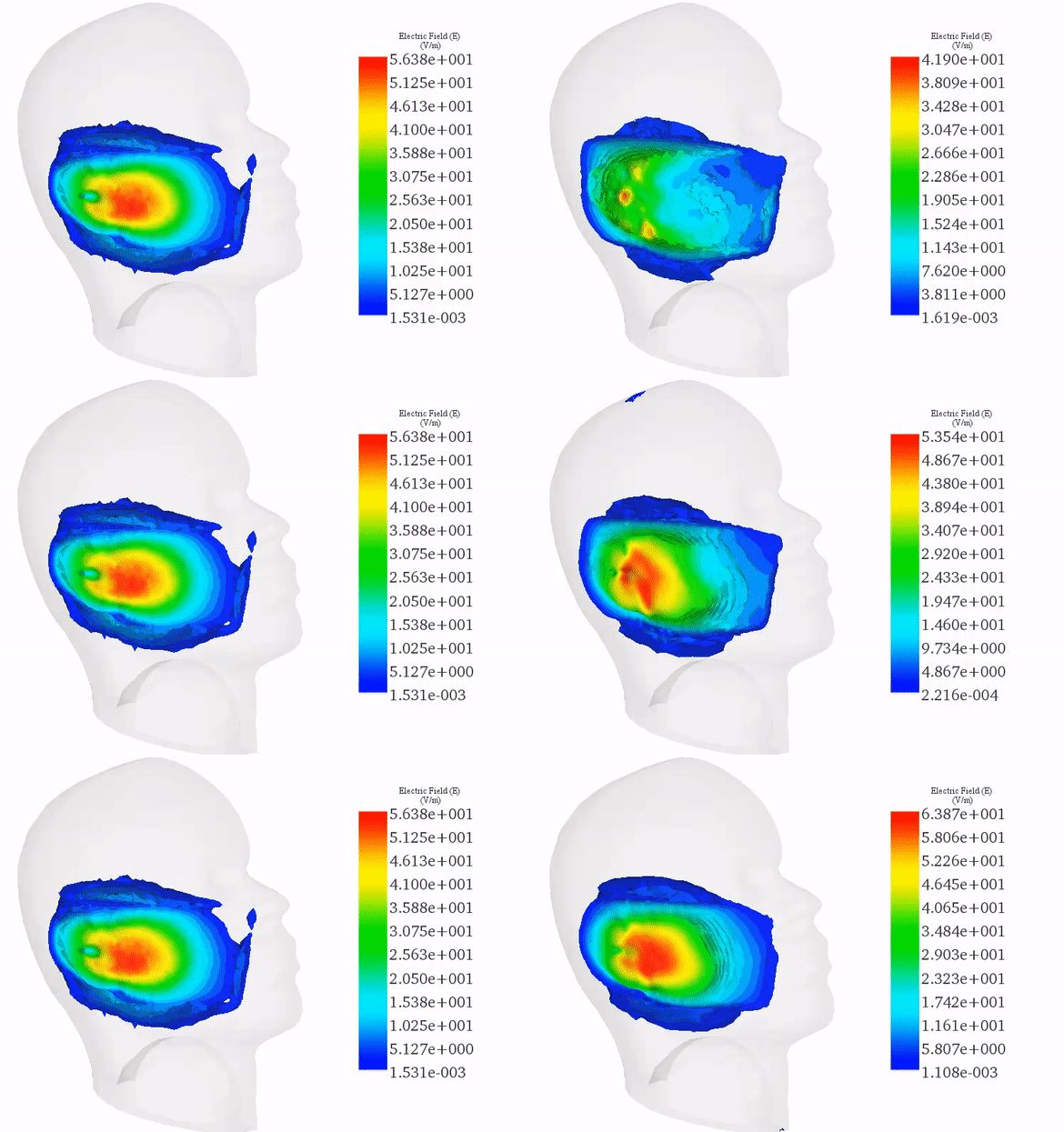
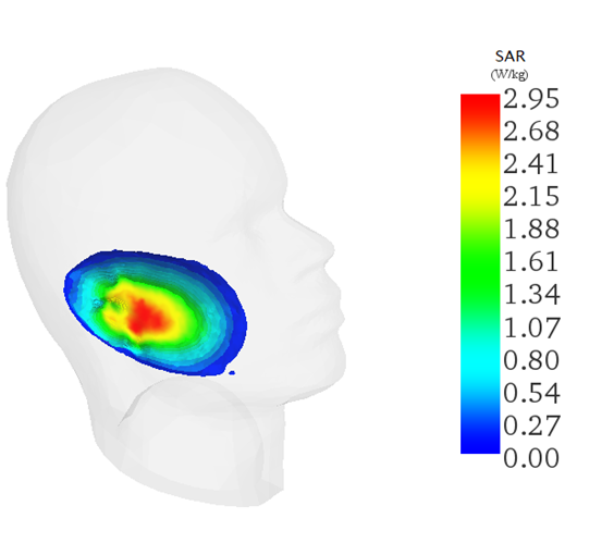
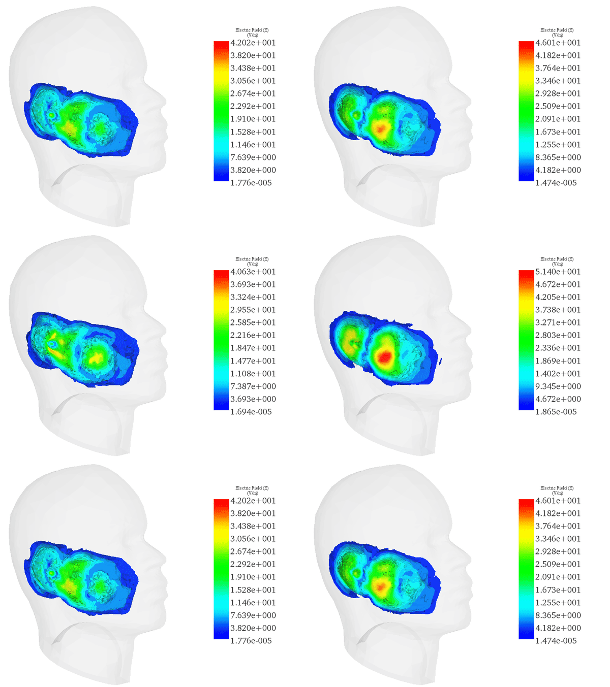
At input powers of 24 dBm (250 mW) for 900 MHz and 21 dBm (125 mW) for 2450 MHz, electric field and SAR distribution on a human head phantom were analyzed. Results, shown in Figure 6, indicate that both E-field and SAR levels for 900 MHz stay within FCC and ICNIRP safety limits. The highest SAR values were localized near the ear, aligning with the maximum exposure area, yet remained compliant with safety standards.
(a)
(b)
For the high band frequency, specifically at 2.45 GHz, the local SAR within the human head reached a peak of 2.95 W/Kg, with the maximum E-field inside the head tissue measuring approximately 50 V/m, as depicted in Figure 7. This observation aligns with safety standards for this frequency range.
(a)
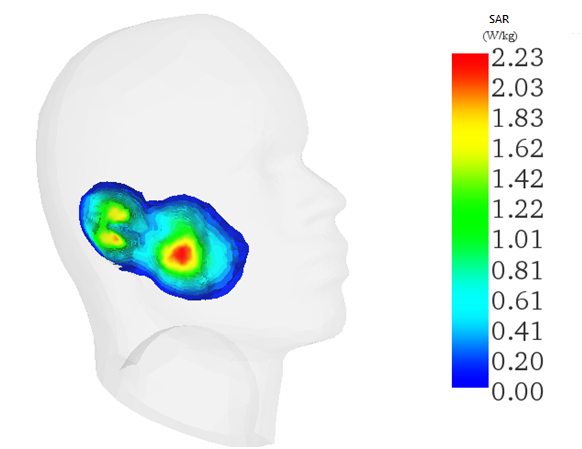
Figure 7 - 3D plot of a) Electric field animation versus phase and b) SAR distribution at 2450 MHz
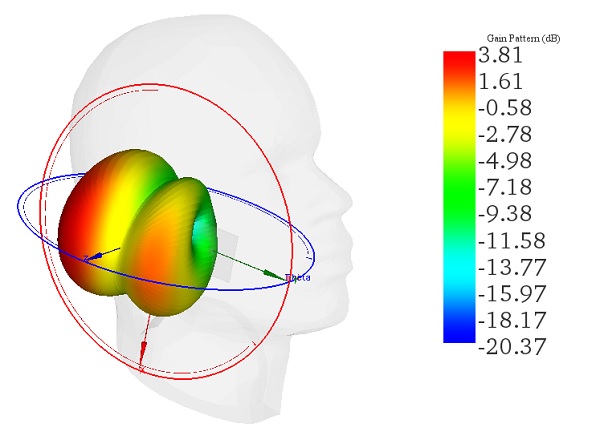
Figure 8 illustrates the gain pattern for the 2.45 GHz frequency, where the maximum gain of 3.81 dB is observed near the human head.
Thermal Analysis
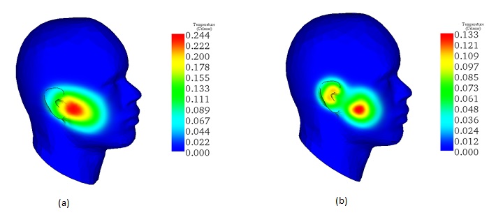
To assess the thermal impact of electromagnetic radiation on human head tissue during a 10-minute call, the transient thermal solver of HFWorks was utilized. With an input power of 24 dBm (250 mW) for 900 MHz and 21 dBm (125 mW) for 2450 MHz, thermal simulations were conducted.
Figure 9 depicts a local temperature increase observed across the human head tissue near the cell phone antenna position. At 900 MHz, the temperature rises by 0.25°C, while at 2.45 GHz, it increases by 0.14°C.
Conclusion
The study explores the interaction between a printed mobile antenna, designed for GSM/LTE/WLAN applications, and human head tissue, considering electromagnetic fields' health impacts. It analyzes the antenna's performance in free space and near the human head, examining factors like return loss, radiation patterns, and specific absorption rate (SAR). Results show stable radiation characteristics in free space across various frequency bands, with compliant SAR levels for lower frequencies near the human head. However, at higher frequencies, SAR values increase, though remaining within safety standards. Thermal analysis reveals minimal temperature increases in human head tissue during a simulated 10-minute call. The study contributes to understanding the safety implications of mobile antennas on human health, emphasizing compliance with regulatory standards.
References
[1]. Belrhiti, Lakbir, et al. "Investigation of dosimetry in four human head models for planar monopole antenna with a coupling feed for LTE/WWAN/WLAN internal mobile phone." Journal of Microwaves, Optoelectronics and Electromagnetic Applications 16.2 (2017): 494-513.
[2]. https://www.icnirp.org/en/frequencies/radiofrequency/index.html


