Capacitance Calculation of Capacitive Touch Panels
Touch Panel Technology: Revolutionizing Digital Devices
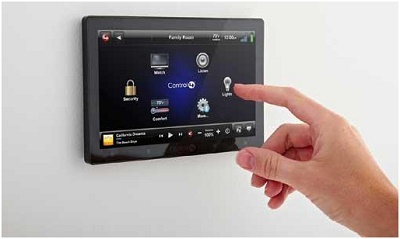
Touch panel technology, featured in smartphones, tablets, digital cameras, and more, revolutionizes user interaction. These panels enable direct screen interaction, bridging display and input functions. Discover the transformative power of touchscreens, making complex tasks accessible and expanding their applications in various industries. Explore capacitive touch panels in-depth below.
Capacitive Touch Panels: A Closer Look
Capacitive touch panels identify touch points by sensing electrical current changes or electrostatic capacity fluctuations upon contact. These panels react to the human body's electrical capacity, allowing pointer-like movements on the screen. Explore two types: surface capacitive and projective capacitive touch panels, each with distinct internal structures.
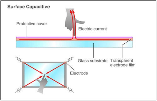
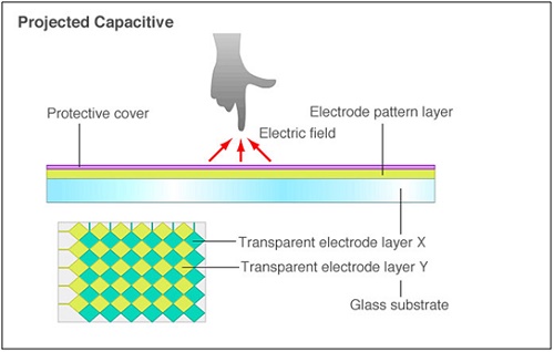
Figure 3 - Projective capacitive touch panels
Analyzing Capacitive Touch Panels with EMS Electrostatic Module
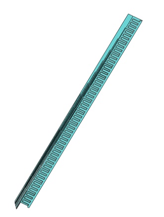
Materials
In EMS Electric Electrostatic analysis, the primary property requirement is the relative permittivity of the material (Table 1).
| Components / Bodies | Material | Relative permittivity |
| Inner Air | Air | 1 |
| Outer Air | Air | 1 |
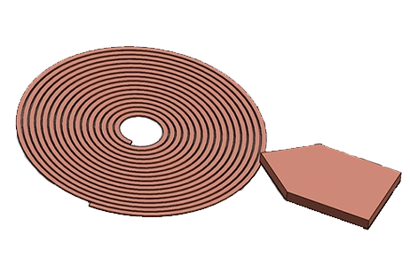
| Touch Panel (18 bodies) | Copper | 1 |
Load and Restraint
In this study, one part of the touch panel will be labeled as a ground, and the other parts (17 parts) as floating conductors.
Meshing
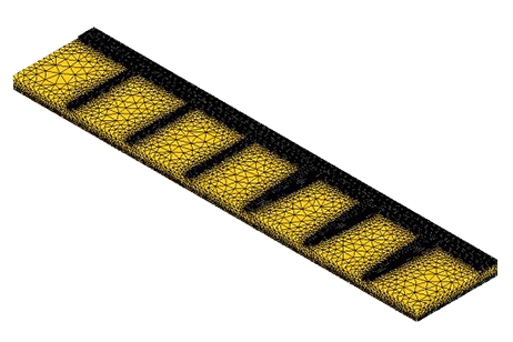
Meshing is vital in design analysis. EMS calculates the element size based on volume, surface area, and geometry. Mesh size and quality depend on geometry, element size, tolerance, and control. In the preliminary analysis, larger elements offer speed, while smaller ones ensure accuracy. Use Mesh Control on solid bodies and faces to adjust mesh quality.
Result
Following the simulation, multiple results are available. EMS' Electric Conduction module computes and visualizes the Electric Field (Figure 5), Displacement Field (Figure 6), and Potential (Figure 7). A results table includes capacitance values for the floating conductors (Table 2).
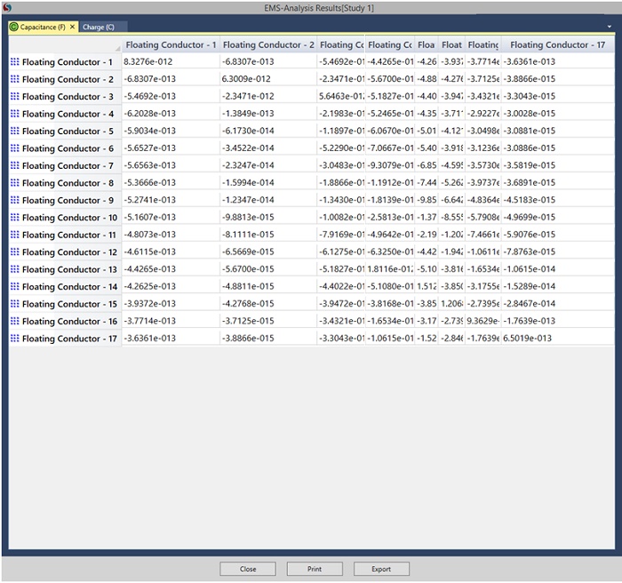
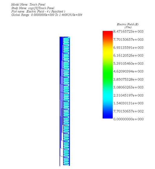
Figure 6 - Electric Field in touch panel
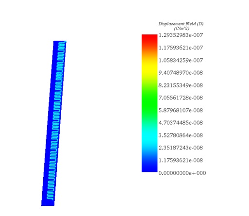
Figure 7 - Displacement Field
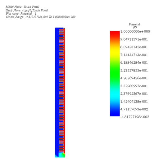
Conclusion
Touch panel technology has significantly transformed user interaction with digital devices like smartphones, tablets, and digital cameras, making complex tasks more accessible and intuitive. Capacitive touch panels, in particular, have played a pivotal role in this transformation by identifying touch points through changes in electrical current or electrostatic capacity, reacting to the human body's electrical properties. This application note delves into the analysis of capacitive touch panels, specifically surface capacitive and projective capacitive types, utilizing the EMS Electrostatic Module for a detailed examination of their capacitance and electric field strength.
The EMS analysis involves assigning materials with specific relative permittivity, defining boundary conditions, conducting thorough meshing, and executing the solver to assess electric conduction, excluding air modeling for precision. Results from the simulation, including electric field, displacement field, and potential visualizations, along with a capacitance matrix, highlight the sophisticated capabilities of EMS in evaluating touch panel performance. This comprehensive analysis underscores the importance of touch panel technology in enhancing device usability across various industries, emphasizing the critical role of capacitive touch panels.


