Analyzing Coaxial Antenna Performance in the 2-4 GHz Band
A Coaxial Antenna
The coaxial antenna, a vertically polarized omnidirectional design, has evolved from Arnold B. Bailey's 1939 patent for a vertical antenna with coaxial element sleeve structures to Bonnie Crystal's 2006 innovation for a more compact, efficient antenna with broad bandwidth capabilities. This example focuses on a basic coaxial antenna model—a quarter-wavelength section of coaxial cable with separated inner and outer conductors, operating between 2 GHz and 4 GHz. It delves into the antenna's design and performance with further descriptions and plots.
.jpg)
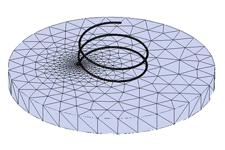
Figure 1 - Geometry of the coaxial antenna
Simulation
This simulation aims to provide a comprehensive analysis of the antenna's performance between 2 and 4 GHz. It will enable visualization of radiation patterns, calculation of the reflection coefficient at the port, and examination of both near and far field distributions using 2D and 3D plots. This approach offers a detailed view of the antenna's operational characteristics and effectiveness in various frequency ranges.
Load/ Restraint
The coaxial antenna design includes a Perfect Electric Conductor (PEC) volume along the conductor's stem, with the input port located on the Teflon surface between the ground and signal conductors. Radiation boundaries are assigned to the lateral surfaces of the air box to accurately model the antenna's interaction with its surrounding environment, facilitating the simulation of its performance characteristics.
Results
The chart displaying the antenna's return loss across the 2 to 4 GHz frequency band indicates a stable reflection coefficient throughout this range. By narrowing the frequency step, the curve's smoothness can be enhanced without significant changes in the reflection coefficient's magnitude, demonstrating consistent performance across the specified frequency band.
.jpg)

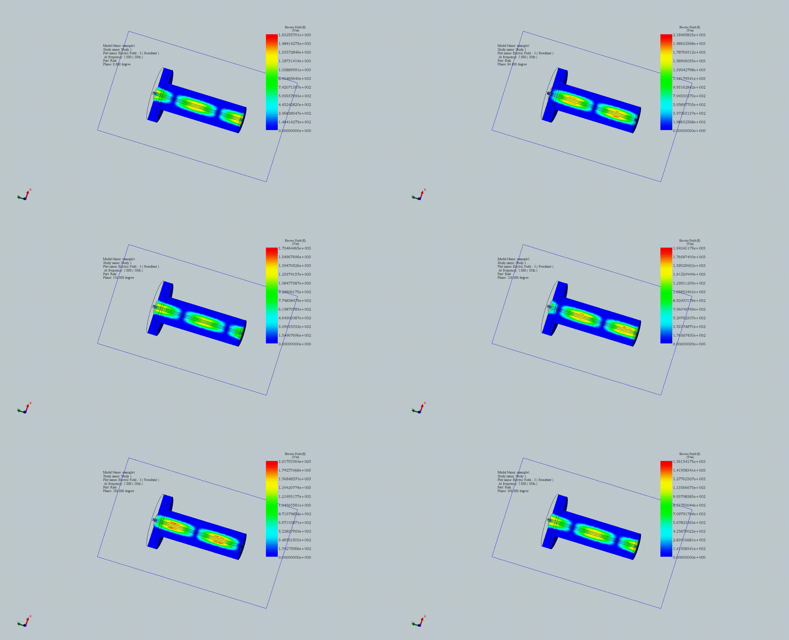
Figure 2 - Wave propagation in the antenna at 2 GHz
The animation illustrates wave propagation within the coaxial antenna, utilizing HFWorks' section clipping feature for detailed internal visualization. This tool allows viewers to observe how electromagnetic waves travel through the antenna structure, enhancing understanding of its operational dynamics.

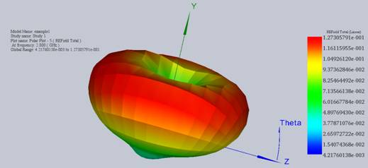
Figure 3 - Radiation pattern of the antenna
Adjusting the chart scale and angle steps can refine the visualization of a 3D electric field radiation pattern, which might appear rough due to initial settings. By setting precise minimum and maximum values, a clearer view of the electric field distribution is achieved, enhancing the analysis and interpretation of the antenna's performance characteristics.
Conclusion
This application note analyzes the design and performance of a basic coaxial antenna, operating within the 2 GHz to 4 GHz frequency band. Originating from innovations dating back to 1939, the modern coaxial antenna's development emphasizes compactness, efficiency, and broad bandwidth capabilities. The simulation conducted offers a deep dive into the antenna's operational dynamics, showcasing radiation patterns, reflection coefficients, and electromagnetic wave propagation through both near and far field distributions. Key to the design is the use of a Perfect Electric Conductor (PEC) and strategic placement of the input port to optimize signal transmission. Results from the simulation reveal a stable reflection coefficient across the operational bandwidth, affirming the antenna's consistent performance. Detailed visualizations, facilitated by HFWorks' advanced features, enable a comprehensive understanding of wave propagation and field distribution, highlighting the coaxial antenna's effectiveness as a vertically polarized, omnidirectional solution suited for a range of applications.


