Transforming Autodesk Inventor into Your Design Platform for Magnetic Lifting Machines
Design Challenges
Designing electromagnetic lifting machines requires engineers to confront several challenges, among which the balance of magnetic force versus power consumption and heat dissipation stand out as critical to the functionality and efficiency of the end product. Here, we'll delve into these challenges and explore how they can be effectively managed using advanced simulation tools like EMWORKS and Autodesk Inventor.
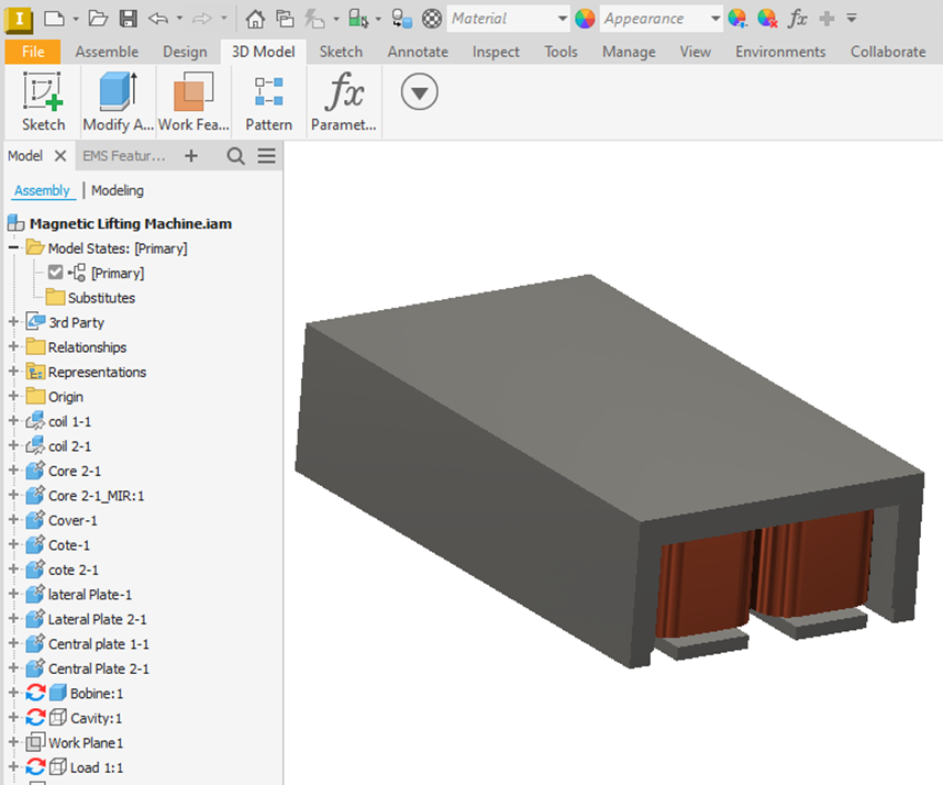
Autodesk Inventor 3D model of the Lifting Machine
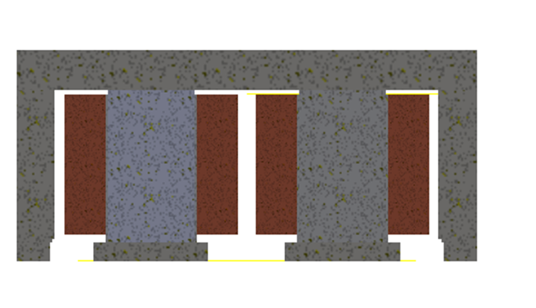
Autodesk Inventor Section View of the Lifting Machine
Magnetic Force Vs Power Consumption
When designing electromagnet-based lifting machines, a core objective is to produce enough magnetic force to handle significant loads without expending excessive power. Understanding the relationship between magnetic force and power consumption is fundamental to achieving an optimal design. The power consumption for electromagnets primarily depends on the coil current, which in turn is a function of the voltage applied. For a fixed voltage scenario, power consumption increases linearly with an increase in coil current.

Lifting Machine with the Load
Detailed Analysis of Magnetic Force Versus Coil Current
The plot depicting magnetic force versus coil current is instrumental in illustrating how variations in current influence the lifting capacity of an electromagnet. The observation of an almost linear relationship between these two variables is pivotal in streamlining the analysis and design of electromagnet-based lifting machines. This linearity not only simplifies calculations but also demonstrates efficient power conversion—where electric power is effectively transformed into magnetic force.
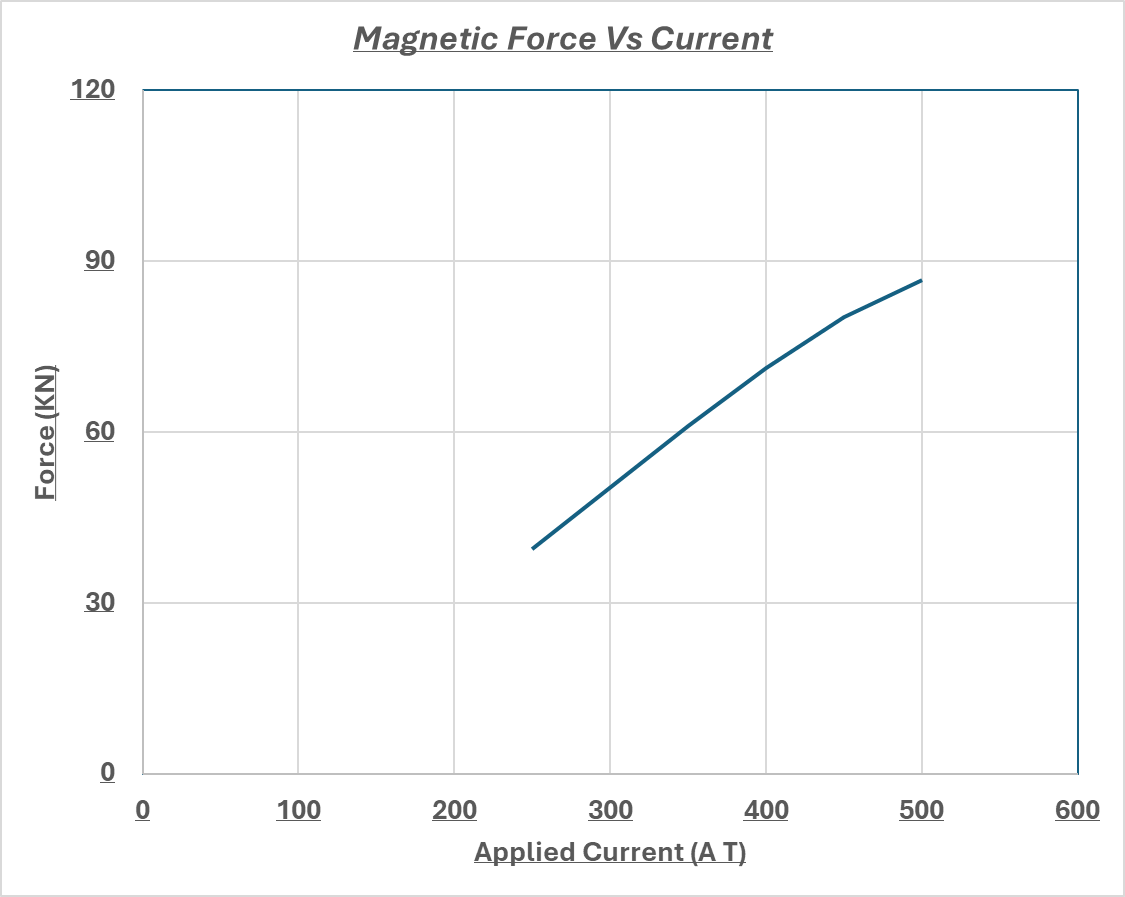
Force (KN) Vs Current (A)
Predictive Control and Design Flexibility
With a linear force-current relationship, engineers gain the ability to predict magnetic force output based on given current inputs. This predictability is crucial in designing lifting systems that can reliably handle specified loads under varying operational conditions.
Efficiency and Performance
The linear relationship indicates minimal energy loss to inefficiencies such as heat or stray magnetic fields at lower currents. This efficiency is critical for maintaining both energy conservation and operational effectiveness, particularly in industries where power cost and equipment endurance are major concerns.
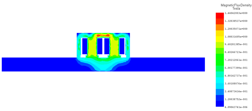
Section View of Magnetic Flux Density for a Current = 250 A.
Operational Limits and Saturation Concerns
While the linear dependency offers numerous design and operational advantages, it's crucial to recognize that this relationship is maintained as long as the core material, typically steel, does not reach its magnetic saturation point. Saturation occurs when all magnetic domains in the steel are aligned, and any further increase in current yields only minor increases in magnetic field strength. Understanding the saturation characteristics of the core material is essential in designing electromagnet systems. If saturation is reached, there will be a disproportionate increase in required power for only minimal gains in force, which can significantly reduce the system's overall efficiency. The magnetic flux density plots for currents of 250 A and 400 A clearly demonstrate a strong dependency of the peak values, and consequently the saturation levels of the steel, on the applied current. These plots effectively highlight how increased current intensifies magnetic saturation, underlining the material's response to electromagnetic forces at different power levels.
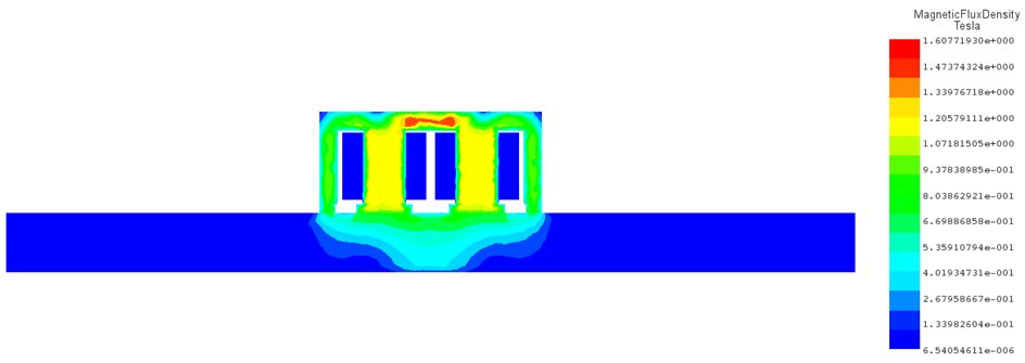
Section View of Magnetic Flux Density for a Current = 400 A.
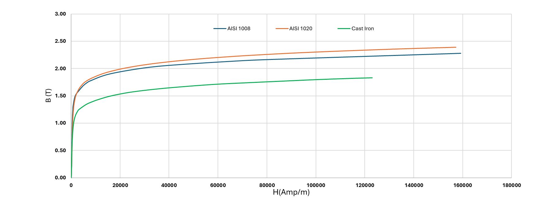
Core BH Curve for Different Steel Grades
Material Selection and Core Design
Selecting core materials with higher saturation thresholds and engineering electromagnets to function optimally within the linear characteristics of their material's magnetic properties is fundamental to boosting overall system performance. Utilizing advanced magnetic materials, such as high-permeability steels or novel alloy compositions, can extend the linear operating range of the electromagnet, allowing for higher force outputs without the risk of saturation. Moreover, precise geometric and structural design of the electromagnet's core can further enhance its efficiency by maximizing the magnetic field density and distribution, ensuring that the device operates reliably within the desired performance parameters. This strategic approach not only improves the lifting capacity and operational reliability but also contributes to energy efficiency and longevity of the electromagnet system.
The electromagnetic force exerted by the lifting machine is influenced by the type of steel used due to variations in their magnetization properties. In tests conducted with three different materials—Cast Iron, AISI 1020, and AISI 1008—the resultant forces were measured at 71.25 kN, 71.77 kN, and 73.41 kN, respectively. This data underscores the significance of material properties on the effectiveness of electromagnetic lifting equipment. Accompanying this text, the magnetic flux density plots for these three steels, using a current of 400 A, are displayed below to further illustrate these differences. The plots reveal that the maximum flux density varies with the steel grade used for the load and core of the machine.
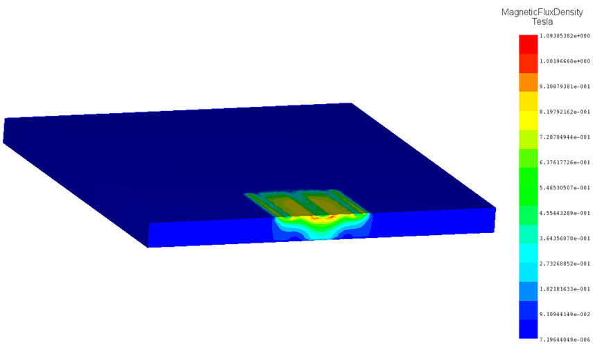
Magnetic Flux Distribution for Steel AISI 1020.
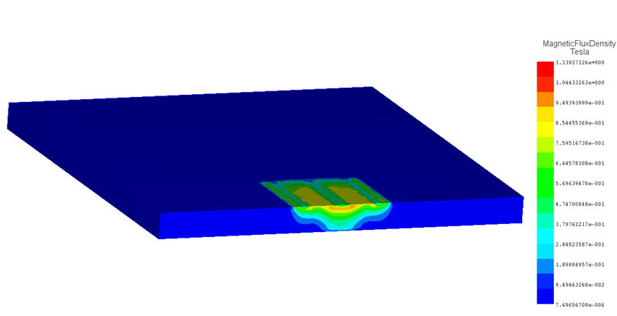
Magnetic Flux Distribution for Steel AISI 1008.
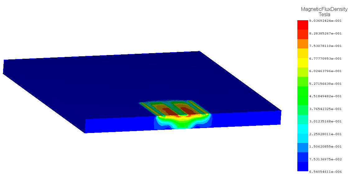
Magnetic Flux Distribution for Cast Iron.
Heat Dissipation and Thermal Management
Effective heat dissipation and thermal management are essential for ensuring the performance, efficiency, and longevity of electromagnet-based lifting machines. As these machines operate, the electrical resistance within the coils generates significant heat, which, if not adequately managed, can accumulate and lead to overheating. This overheating can degrade performance and potentially damage the electromagnet and its components. The heat generated in the coils is directly proportional to the square of the current, meaning that even slight increases in current can cause substantial rises in heat production. The following plots illustrate the temperature distribution within the coil and steel at current values of 250A, 400A, and 500A. As anticipated, the coil exhibits the highest temperature across all scenarios. Furthermore, the maximum temperatures in all cases remain within acceptable limits, indicating no overheating and confirming the system’s design is effectively managing heat dissipation.
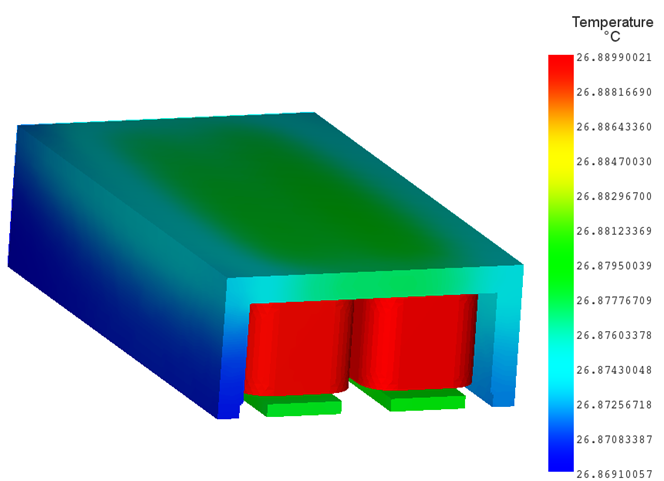
Temperature Distribution for a Coil Current =250 A; Maximum Temp = 26.88° C
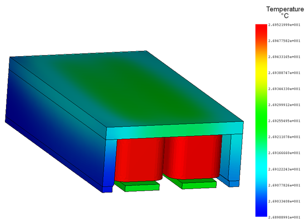
Temperature Distribution for a Coil Current =400 A; Maximum Temp = 26.95° C
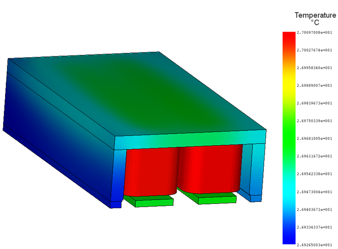
Temperature Distribution for a Coil Current =500 A; Maximum Temp = 27.1° C
Conclusion
Leveraging Autodesk Inventor and EMWORKS for designing electromagnetic lifting machines significantly enhances efficiency and functionality. These powerful simulation tools enable engineers to meticulously balance magnetic force, power consumption, and thermal management, optimizing each design for specific operational needs. This integration not only streamlines the engineering process but also propels the industry forward by setting new benchmarks in safety and energy efficiency. Ultimately, adopting these sophisticated technologies equips companies to meet contemporary challenges in lifting machine applications, driving innovation and ensuring robust, reliable solutions in electromagnetic lifting technology.


