Why Voice Coil Actuators Are Ideal for Precise Positioning?
Voice Coil Actuator
A voice coil actuator, based on the Lorentz force concept, is a type of direct drive mechanism which delivers extremely precise positioning over small displacements. The voice coil is currently used for wide range of applications. Known also as non-commutated DC linear actuator, the voice coil is simple to control, provides high acceleration and speed, presents a compact and lightweight structure. These advantages make it perfect replacement of conventional electric motor in applications where very precise positioning is needed. It can provide high precise displacement for nano or micro positioning applications with strokes from 10nm up to 100mm [1]. This link elaborates when voice coil actuators are preferred.
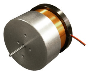
The voice coil actuator consists mainly of permanent magnet and stranded coil winding. Additional ferromagnetic components may be added to improve the efficiency of the actuator. In the voice coil actuator, the moving component can be the coil or the permanent magnet. Figures 2 and 3 show two configurations of the voice coil actuators: moving coil and moving permanent magnet, respectively. The electrical energy converted into mechanical motion inside VCA follows the Lorentz force principle. This mechanism is governed by the following physics law (Lorentz Force): If a conductor is carrying a current and placed in a magnetic field, an orthogonal electromagnetic force is created on this conductor. The force direction can be flipped by reversing the polarity of the conductor current.
The computed Lorentz force is computed using the formula below:
$$ \mathbf{F} = \mathbf{J} \times \mathbf{B} $$ where J is current density flowing inside the conductor and B is magnetic field
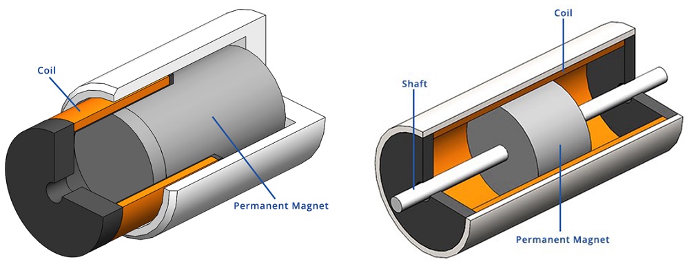
Voice coil actuators are employed in many applications. They are adopted by medical industry in portable ventilators, pumps for metering and dosing, etc. Other leading industries like semiconductors and electronics, which require extremely high displacement resolution, have used voice coil actuators in mounting, assembling and testing products. The low inertia of the moving coil also makes them the preferred choice in auto-focusing motor actuator for smartphones camera and other tiny applications.
Voice Coil actuator Vs Solenoid Actuator
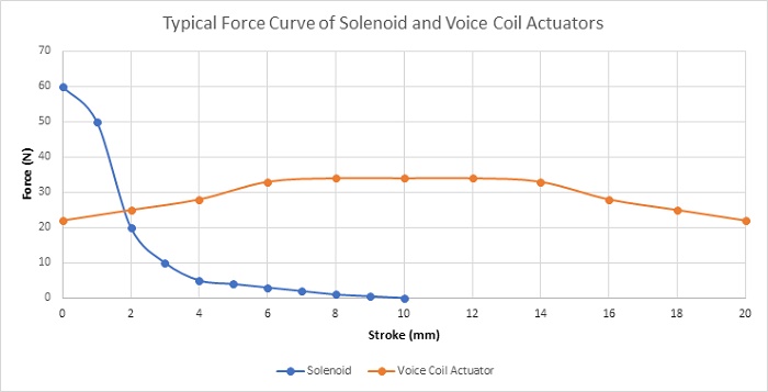
Table below and Figure 3 contains a comparison of the main characteristics and the typical behaviours of the generated force of both voice coil and solenoid actuators. Solenoid produces higher force density in a limited stroke range while the voice coil actuator can create a low but constant force in a wide stroke range. Moreover, the voice coil actuator provides more robust and controllable force.
| Voice Coil Actuator | Solenoid Actuator | |
| Stroke | Up to 5 inches | ¼ inches |
| Force | Low | High |
| Constant Force | Yes | No |
| Reversible | Yes | No |
| Position/ Force Control | Yes | No |
| Cost | Moderate | Low |
Problem description
In this article, a voice coil actuator will be studied [3]. A series of simulations will be performed using the optimal actuator parameters determined in [3]. In the first section, static analysis will be used to compute the Lorentz force of the coil versus both current and actuator positions. Transient magnetic study will be used later to compute the current at different DC voltage excitations. Simulation results will be compared to experimental data published in [3]. Electrodynamic simulation will be used at the end to compute mechanical output data such linear displacement, speed and acceleration of the actuator. Temperature evolution of the voice coil actuator will be studied using an electrothermal analysis with EMS.
EMS, SOLIDWORKS and SOLIDWORKS Motion will be used to carry out the different simulations of the studied voice coil actuator. Figures 4a), 4b) and 4c) show full and cross section views of the studied voice coil device. A stranded coil, made of copper with 760 turns, is free to move axially along the airgap zone created between the ferromagnetic shell and the permanent magnet. The neodymium permanent magnet N42, which is stationary and axially magnetized, is a second source of energy. both the orientor and shell are made of soft iron characterized by its high permeability. The flux orientor is used to guide the field and improve the magnetic circuit path. A bobbin is inserted to support of the coil.

Simulation and Results
Static Simulation -Geometrical Parametric Sweep
First simulations are performed at different DC current rates while changing the position of the moving parts (coil and bobbin). A parametric sweep study is defined to compute the magnetic flux, Lorentz force, the coil parameters, etc. Figures 5a) and 5b) display respectively full and cross section views of the magnetic flux density plots when the applied current is + 10A and the position of the assembly coil and bobbin is 10mm. The average of the magnetic flux is about [1.3T,1.74T]. Front and side cross section views of the magnetic field vector plot are shown in Figure 6a) and 6b). the current density of the coil is 1e8A/m^2.
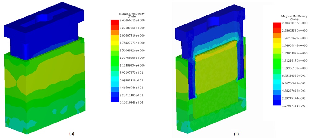
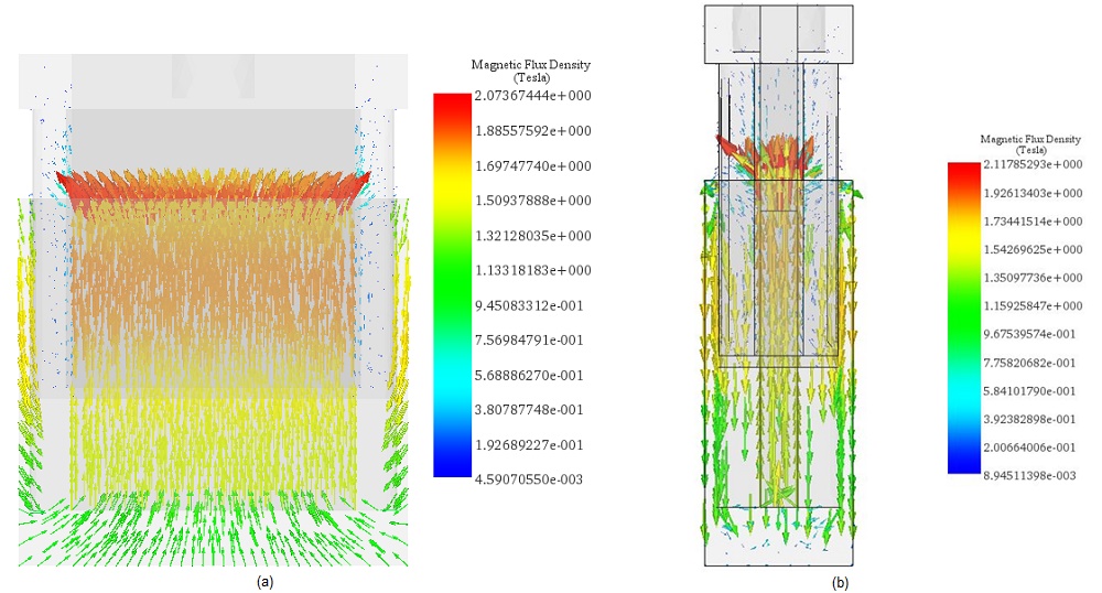
Figure 7 shows experimental [3] and simulation results of the Lorentz force computed at both different DC currents and stroke values. The maximum force ( around 33N) is generated with a current of -10A at 10mm positon. The measured force values from 4 to 16 mm stroke can be considered as constant for the different applied current rates. Constant force rates with larger stroke can help to obtain a higher acceleration. Figure 8 contains a plot of the force peak values for different currents. It demonstrates that the force has a proportional linear relation with the current. This can illustrate the simple and flexible control of the actuator force density.
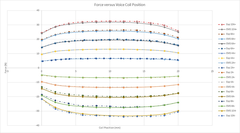
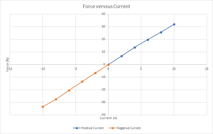
Figure 9 gives the force sensitivity parameter for different input currents along the stroke. This parameter is constant regarding the current and depends only on the coil position. The simulated average value of the force sensitivity parameter (computed by EMS) is about 3.2N/amp which is close the experimental measured value (Exp 3.1N/amp).
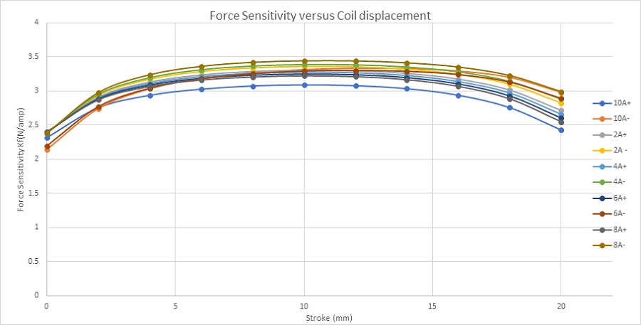
Figure 10 shows the inductance curve versus coil displacement. The inductance decreases from 5mH at 0mm to 4.48mH at 20mm.The variation can be neglected, and the coil inductance can be considered as constant along the stroke.
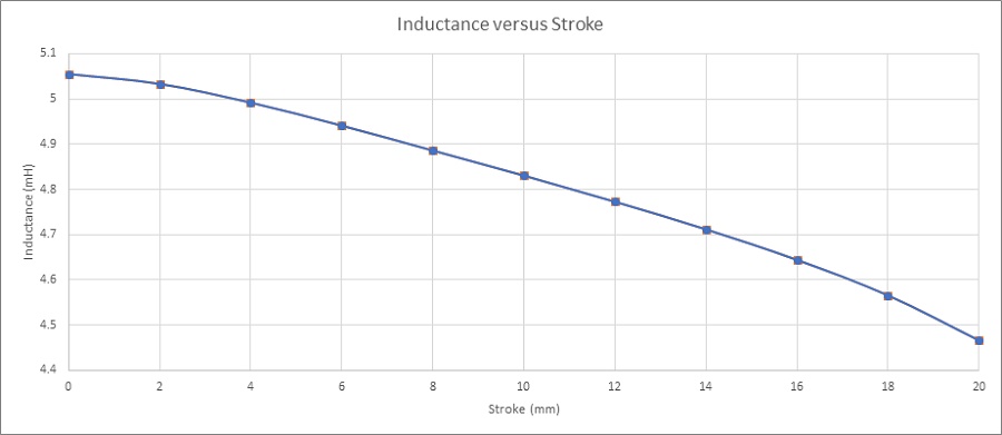
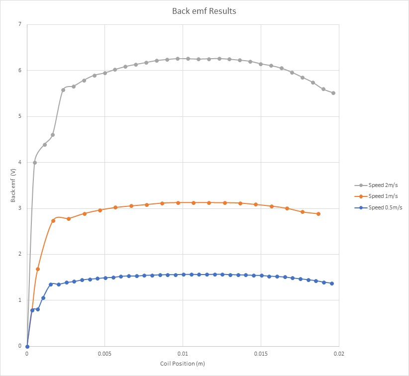
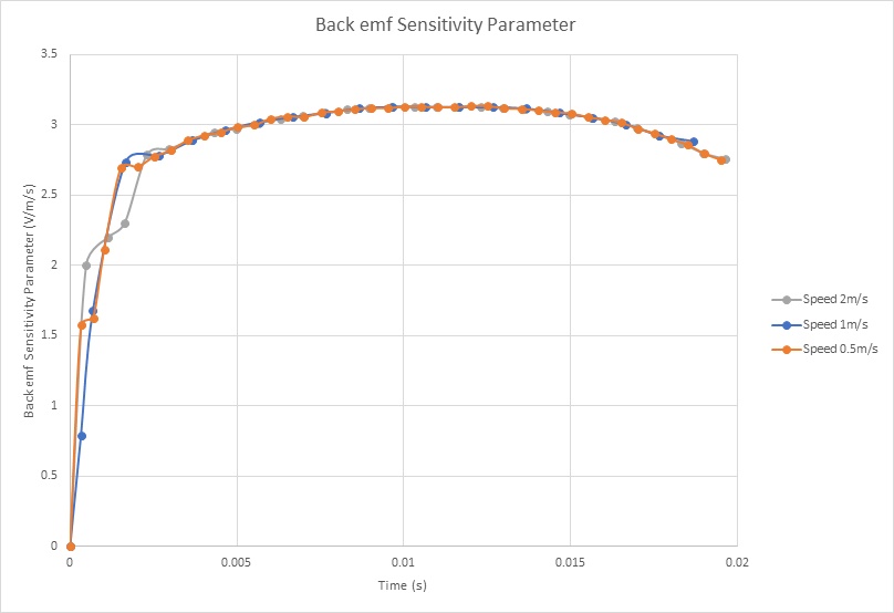
Figure 11 shows the Back emf results of the coil for different velocities and versus the center of mass of the moving components. It demonstrates that the Back emf increases with the speed. With a speed of 2m/s, it reaches a peak of 6.25V. Figure 12 contains the computed Back emf sensitivity parameter (V/speed) versus the coil position. It is a speed-constant parameter, i.e. it doesn’t change with the speed of the coil. It can be averaged to 3.1 V/m/s.
| EMS | Experimental | |
| Current | +10 A$$ \leq I \leq $$-10A | +10A$$ \leq I \leq $$-10A |
| Resistance | 20.35 $$ \Omega $$ | 20.5$$ \Omega $$ |
| Inductance | 5mH | 5mH |
| Maximum Generated Force | 34N | 33.4N |
| Force Sensitivity Parameter | 3.2N/amp | 3.1N/amp |
| Back emf Sensitivity Parameter | 3.1V/m/s | 3.1V/m/s |
Transient Simulation using EMS – Current and force calculation for different voltages
In this section, electromagnetic simulation is performed using Transient module of EMS. The coil is supplied with a range of DC voltages. Magnetic fields, current and Lorentz force are computed. Figure 13 shows the magnetic flux density when the steady state is achieved.
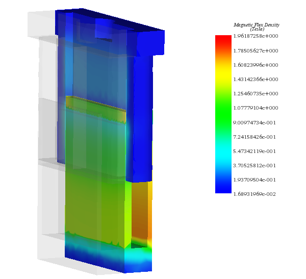
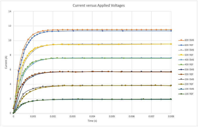
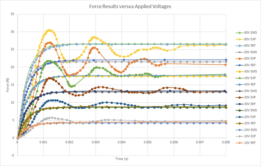
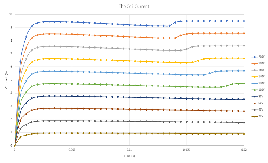
Figure 14 illustrates the calculated current response versus different applied voltage rates. It shows that the steady state is reached in 2ms. This can help to improve the time response of the system. The computed currents are 2A and 11A when 10V and 60V are respectively applied to the stranded coil. Figure 15 contains several plots of the force results at the same static position (12mm). The plotted curves of the force measured by experimental tests contain few oscillations before achieving the steady state. A force of 4.5N is obtained when a DC voltage of 10V is applied while it is 26N when the applied DC voltage is 60V. The higher the voltage the higher the force is.
Electro-Mechanical Simulation using EMS Coupled to SOLIDWORKS Motion – Coil displacement, speed, acceleration and current calculation
In this section, electrodynamic simulation is established to calculate and generate electromechanical results including magnetic fields, current, coil position, speed and acceleration, etc. Eddy current effect caused by motion is neglected. EMS coupled to SOLIDWORKS motion analysis is used to run these simulations. Figures 16a) contains a plot of the magnetic flux density at 20ms and 20V. It shows that the maximum field (1.77T) is located at the thin walls of the iron shell. At 20ms, both Current and position of the coil are 0.88A and 4.78mm, respectively. Figure 16b) gives a plot of the magnetic flux at 9ms and 200V. The peak values of the magnetic flux are about 2T and reached in the iron shell. The coil achieves a position of 8.6 mm and a current of 9.26A at this instant. Magnetic fields animation are shown in Figures 17a) and 17b).
-in%20case-of-20V-b)in-case-of-200V.jpg)
%20.gif)
(a)
.gif)
(b)
Figures 18 a) and 18b) and 18c) display the results of coil linear displacement, speed and acceleration for different applied voltages. For a DC voltage of 20V, the voice coil actuator moves from 0 mm at 0s to 4.7mm at 20ms. The maximum reached speed by the coil is nearly 0.5 m/s while the acceleration is about 30 m/s^2. When a 200V DC voltage is applied to the actuator, the moving coil goes from 0 mm to 20 mm in 13ms. This leads to a maximum speed and acceleration of 3.3 m/s and 308 m/s^2, correspondingly. The higher the voltage, the higher is the speed. This can be explained by Figure 19. Lorentz force increases with the current which is directly proportional to the applied voltage. The computed currents in the coil are 9.5A and 0.9A when the supplied voltages are respectively 200V and 20V.
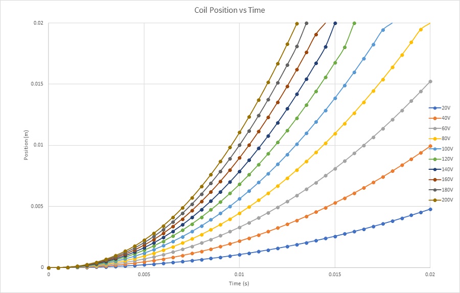
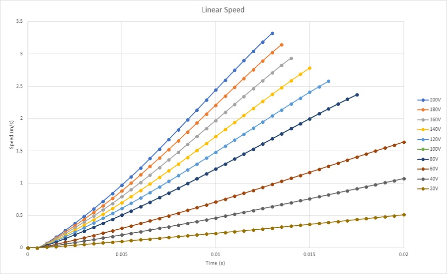
Figure 18b - Coil speed
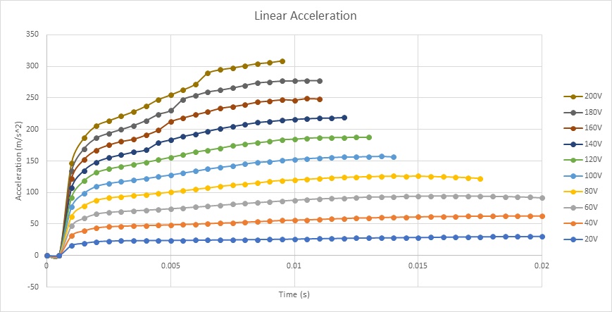
Figure 18c - Coil acceleration
Electrothermal Analysis – Winding loss and temperature calculation of the voice coil actuator
This analysis will focus on the electromagnetic losses and the temperature generated in the voice coil actuator. Since eddy effect is neglected, copper losses (winding losses) are the main electromagnetic losses in this actuator. Due to the Joule law, current flowing the winding conductors generates a heat -called Joule heat. Hence, the temperature of the voice actuator will rise quickly and proportionally to the applied voltage.
Transient electrothermal analysis is carried on using EMS to compute winding losses and temperature evolution versus time into a static position of the coil. EMS allows thermal coupling analysis without any export/import data. Electromagnetic time constant is too small compared to thermal time constant, i.e the steady state of the electromagnetic solution will be reached in very small time while achieving the steady state regime of the thermal analysis will take much longer time. Therefor, different simulation end times/time step sizes should be used to accelerate the analysis.
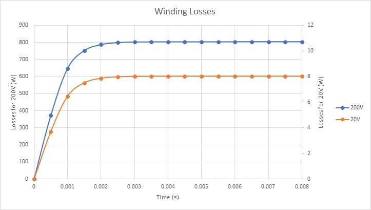
Figure 20 shows the winding loss results for two different voltages. Copper losses in the voice coil are about 800W and 8W when 200V and 20V DC voltages are applied respectively.
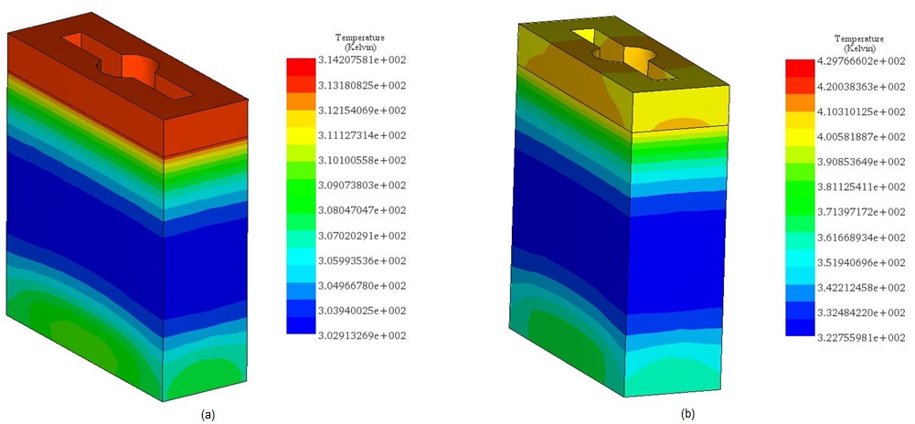
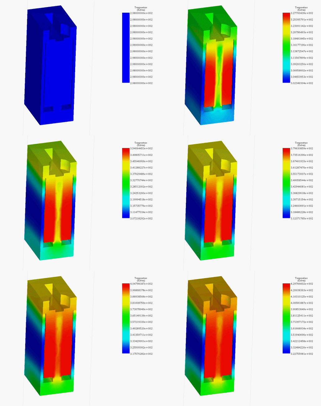
Figures 21a) and 21b) display the final temperature of the voice coil actuator for 20V and 200V, respectively. The temperature is generated inside the coil, due to copper loss, then it propagates to the whole system by conduction and convection.
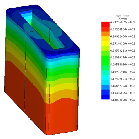
The temperature reaches a peak value of 314 K after 60s in the case of 20V while it rises from 300 K ambient temperature to 429 K in 5 seconds. Figure 22 contains the temperature results in case of 200V at 5s. It confirms that the coil is the source of heat in this case. Temperature evolution for the whole system is shown in Figure 23.
Conclusion
This application note thoroughly investigates the capabilities and applications of a voice coil actuator (VCA), emphasizing its precision in small displacement movements based on the Lorentz force principle. VCAs stand out for their simple control, high acceleration, speed, compactness, and lightweight features, making them ideal for precise positioning needs in various fields, from medical devices to semiconductor manufacturing. The analysis, supported by EMS simulations, delves into the actuator's performance under different electrical conditions, showcasing how current changes affect the Lorentz force generated, thereby influencing the actuator's movement and force output. Additionally, the electrothermal analysis highlights the thermal effects of the operation, particularly how copper losses contribute to temperature rise, critical for understanding the actuator's efficiency and safety in prolonged use. By comparing simulation results with experimental data, the study not only validates the VCA's design and operational principles but also underscores its versatility and reliability in applications demanding high precision and control. The comparative analysis with solenoid actuators further illustrates the VCA's superior performance in providing consistent force over a wide stroke range, enhancing its suitability for advanced technological applications.
References
[1]: https://www.linearmotiontips.com/when-are-voice-coil-actuators-best-linear-motion-option/
[2]: https://www.machinedesign.com/mechanical-motion-systems/article/21836669/what-is-a-voice-coil-actuator
[3]: Vahid Mashatan. Design and Development of an Actuation System for the Synchronized Segmentally Interchanging Pulley Transmission System (SSIPTS). Department of Mechanical and Industrial Engineering University of Toronto 2013


