Design and Simulation of a Heavy-Duty Lifting Machine
A Magnetic Lifting Machine
A lifting machine (Figure 1) utilizes magnetized steel components as electromagnets for lifting heavy metallic items like scrap metal and steel plates. Permanent Magnetic Lifters excel in handling steel plates, blocks, and press molds, facilitating loading/unloading during operations. Ideal for moving iron blocks and magnetic materials, they offer simplicity, safety, and efficiency in factories, docks, warehouses, and the transport sector, enhancing working conditions and productivity.
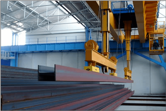
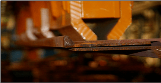
Figure 1 - Magnetic Lifting Machine Description
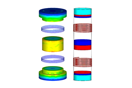
This example involves a magnetostatic analysis of a lifting machine (Figure 2), featuring magnetized steel components and a steel plate positioned a short distance from the electromagnet. The device is energized through a coil wound around it, with current serving as the excitation source. Utilizing EMWorks' EMS software, the analysis calculates the magnetic flux within the machine and the resultant force exerted on the steel plate.
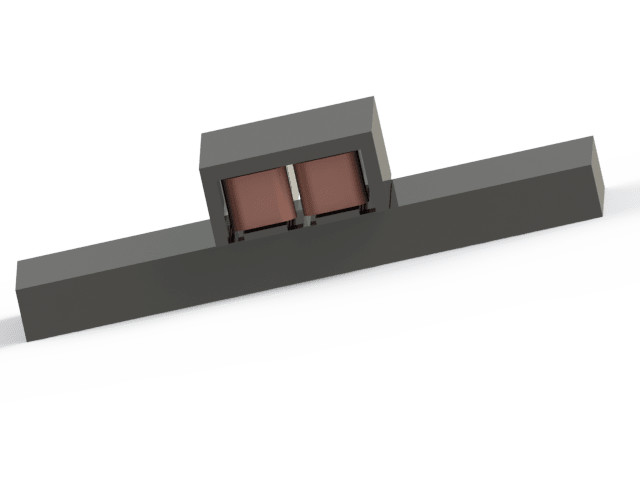

Figure 2 - 3D Model of the Magnetic Lifting Machine
The Study
The Magnetostatic module of EMS is employed to calculate and illustrate the magnetic flux and intensity in the coil, steel lifting components, steel plate, and the air gap between them. Additionally, it assesses the coil's inductance and the electromagnetic force exerted on the load, i.e., the steel plate. The analysis includes stranded coils, each comprising 5*6000 ampere-turns.
Materials
For the Magnetostatic study, the key parameter required is the relative permeability of each material, as detailed in Table 1.
Table 1 - Table of materials
| Components / Bodies | Material | Relative Permeability |
| Coil 1 | Copper | 0.99991 |
| Coil 2 | Copper | 0.99991 |
| Air Box | Air | 1 |
| Core 1 | AISI 1008 Steel | Non linear |
| Core 2 | AISI 1008 Steel | Non linear |
| Cover 1 | AISI 1008 Steel | Non linear |
| Load | Typical Steel | Non linear |
| Central Plate 1 | AISI 1008 Steel | Non linear |
| Central Plate 2 | AISI 1008 Steel | Non linear |
| lateral Plate 1 | AISI 1008 Steel | Non linear |
| lateral Plate 2 | AISI 1008 Steel | Non linear |
| Cote 1 | AISI 1008 Steel | Non linear |
| Cote 2 | AISI 1008 Steel | Non linear |
Results
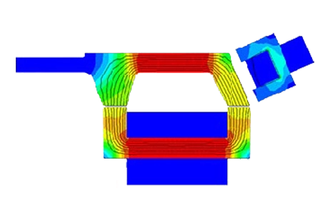
Fringe and vector plots depicting the magnetic field are presented in Figures 3 and 4, respectively. The magnetic flux exceeds 1.8 Tesla at the cores of the electromagnets and ranges between 1.2 to 1.4 Tesla within the steel load. A cross-sectional view of the vector plot is illustrated in Figure 5.
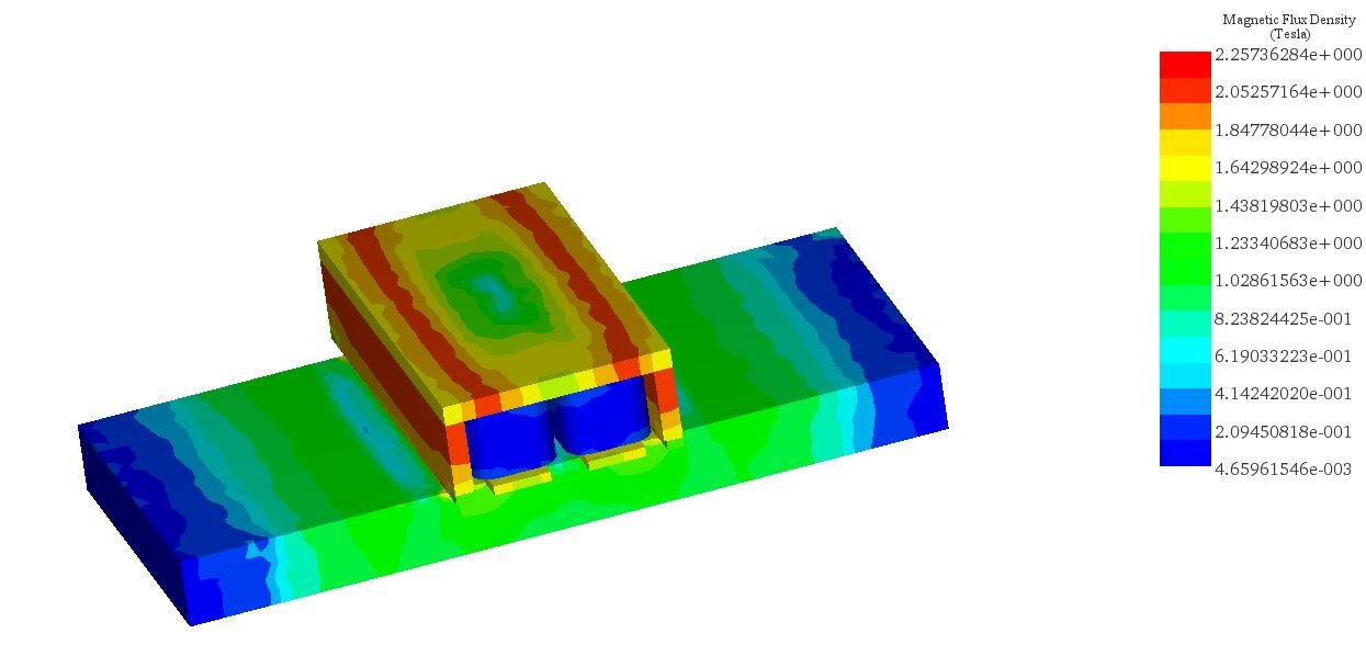
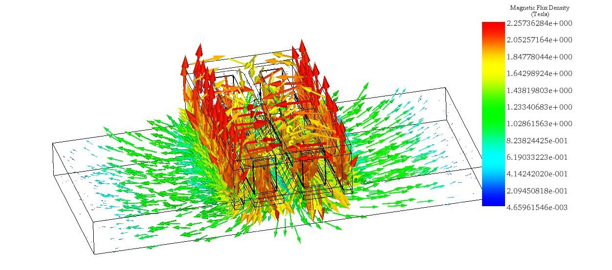
Figure 4 - Magnetic Flux Density vector plot
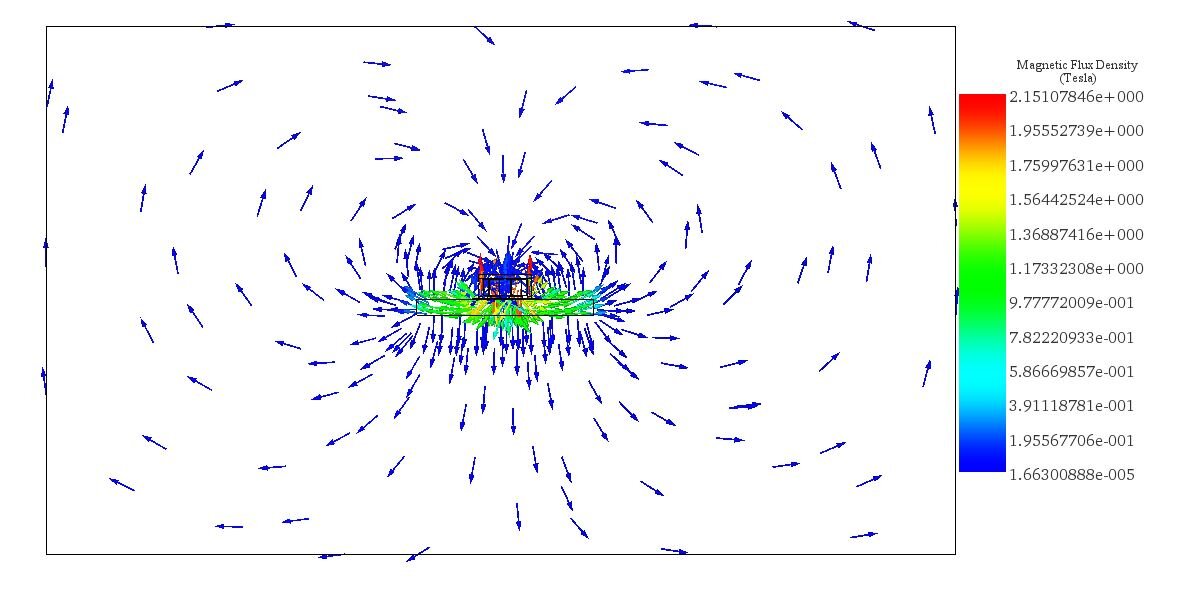
Figure 5 - Cross-section view of the vector magnetic field plot
Conclusion
The magnetic lifting machine, utilizing magnetized steel components and electromagnets, is analyzed using EMWorks' EMS software for magnetostatic properties. The study focuses on calculating the magnetic flux and intensity within the machine, as well as the electromagnetic force exerted on a steel plate load. Through the Magnetostatic module of EMS, the analysis incorporates stranded coils with significant ampere-turns and considers the relative permeability of various materials, including copper and AISI 1008 steel. The findings, illustrated through fringe and vector plots, reveal a magnetic flux density exceeding 1.8 Tesla at the electromagnets' cores and between 1.2 to 1.4 Tesla within the steel load. The machine generates a significant force of approximately 1.14×10⁵ Newtons on the load, demonstrating its efficiency in lifting heavy metallic items. This technology promises enhanced safety, simplicity, and productivity in various industrial applications, improving working conditions and operational efficiency in sectors like manufacturing, warehousing, and transportation.


