Electric Field Inside the Cavity of a Charged Sphere
Physics
The superposition principle is a fundamental concept in physics. It tells us that when a complex excitation can be broken down into smaller parts, the total response is simply the sum of the responses to each individual part. To better understand this principle, let's consider an electrostatic example.
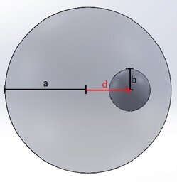
Imagine a sphere with a radius of 1 meter that contains an empty spherical cavity with a radius of 0.25 meters. Inside this sphere, there is a positive volume charge density $$ \rho = 10^{-6} \, \frac{C}{m^3} $$ The center of the cavity is at the distance $$ d = 0.5 \, \text{m} $$ from the center of the charged sphere (Figure 1).

Figure 1 - Positively charged sphere with an off-centered cavity
According to the superposition principle, total field inside the cavity can be found by adding up individual fields of:
A positively charged ( $$ \rho = 10^{-6} \, \frac{C}{m^3} $$ ), thoroughly filled sphere with a radius $$ a = 1 \, \text{m} $$ .
A negatively charged ( $$ \rho = -10^{-6} \, \frac{C}{m^3} $$ ) sphere whose size and position match the cavity (Fig. 2).

Figure 2 - Representation of an empty volume by a superposition of two opposite charge density domains
The electric field within the interior of an isolated, uniformly charged sphere at a distance
from its center can be determined using Gauss' Law.
Which yields for a positive sphere:
$$ \stackrel{\rightarrow}{E} = \frac{\rho}{3 \epsilon_0} \stackrel{\rightarrow}{r_1} $$
And for a negative sphere:
$$ \stackrel{\rightarrow}{E}_{-} = - \frac{\rho}{3 \epsilon_0} \stackrel{\rightarrow}{r_2} $$
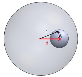
Where vectors $$ \stackrel{\rightarrow}{r_1} $$ and $$ \stackrel{\rightarrow}{r_2} $$ are as defined in Figure 3.

Figure 3 - Relationship between the individual Electric field directions and the vector representing the cavity offset
Therefore, the total electric field in the cavity can be computed as:
$$ \stackrel{\rightarrow}{E} = \stackrel{\rightarrow}{E}_{+} + \stackrel{\rightarrow}{E}_{-} = \frac{\rho}{3 \epsilon_0} \left( \stackrel{\rightarrow}{r_1} - \stackrel{\rightarrow}{r_2} \right) $$
$$ \stackrel{\rightarrow}{E} = \frac{\rho}{3 \epsilon_0} \stackrel{\rightarrow}{d} $$
From the last equation, it can be concluded that the electric field in the cavity is constant with a direction $$ \stackrel{\rightarrow}{d} $$ and that its magnitude (for $$ d = 0.5 \, \text{m} $$ and $$ \rho = 10^{-6} \, \text{C/m}^3 $$ ) is $$ E = 18.832 \, \frac{\text{kV}}{\text{m}} $$ The field magnitude depends only on the value of the charge density and the distance by which the center of the cavity is offset from the center of the sphere.
Model
Creating an Air domain
In EMS, electromagnetic analysis often necessitates the modeling of the surrounding air regions because the electromagnetic field can extend beyond the parts of the simulated system. To incorporate the air domain into the assembly, you should follow these steps:
- Select the Air part in the Solidworks feature manager
- Click Edit component
 in the Solidworks Assembly tab
 - In Solidworks menu click Insert/Molds/Cavity
- In the cavity feature manager, select Charged sphere and Cavity as the Design Components
- Click OK
 .
.

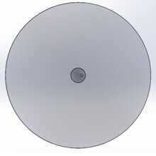
Figure 4 - 3D model of sphere with a spherical cavity together with surrounding air domain
The simulation is performed as the EMS Electrostatic study![]() . Air is used as a material for all parts.
. Air is used as a material for all parts.
(To see how to assign materials, see the “Computing capacitance of a multi-material capacitor” example).
Boundary conditions
To simulate the electric field, you should follow these boundary condition assignments:
- Assign a Charge Density boundary condition to the large sphere. This will specify the charge distribution on the surface of the sphere.
- Assign a Fixed Voltage boundary condition to the face of the Air region. This will set a fixed voltage on the specified face of the air region, which will interact with the charge distribution on the large sphere to determine the electric field.
To assign a charge density to the Charged sphere:
- In the EMS manger tree, Right-click on the Load/Restraint
 , select Charge density
  , then choose Volume.
 - Click inside the Bodies Selection
 box and then select the Charged sphere.
 - In the Charge Density tab, type 1e-006.
- Click OK
 .
.
To see how to assign 0 Volt to the face of the Air region, see “Force in a capacitor” example.
Results
To display the variation of the electric field along the axis that connects the center of the Charged sphere and the center of the cavity:
- In the EMS manger tree, Under Results
 , right click on the Electric Field folder
  and select 2D Plot then choose Linear.
 - The 2D Electric Field Property Manager Page appears.
- In the Select points tab, select the start and the end points.
- In the Number of Points tab, type 1000.
- Click OK
 .
.
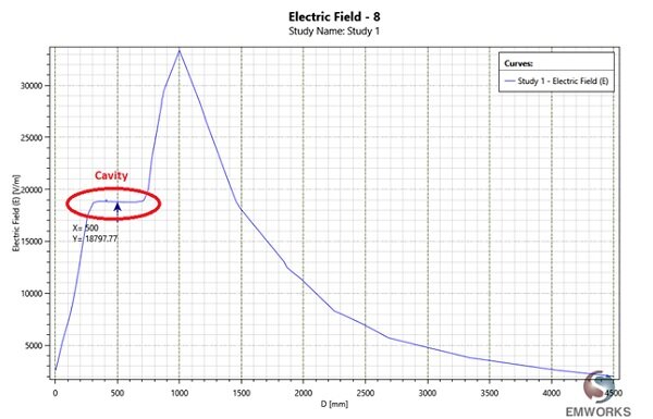
In the obtained curve (Figure 5), it’s clear that the electric field in the cavity is constant, and its value is $$ E = 18.797 \, \text{K volts} $$, which closely matches the theoretical result. The field in Figure 5 steadily increases with the radius until it meets the cavity $$ r = 250 \, \text{mm} $$ and then remains unchanged through the cavity (till $$ r = 750 \, \text{mm} $$ ). The field peaks at the surface of the sphere ( $$ r = 1000 \, \text{mm} $$ ) and then it drops with the square of radius.

Conclusion
References
[1] http://jkwiens.com/2007/10/24/answer-electric-field-of-a-nonconducting-sphere-with-a-spherical-cavity/


