Study of a MMMS-based Tactile Micro-Actuator
Magnetic Micro-Actuator
This application note explores a tactile micro-actuator utilizing Micro-magneto-mechanical systems for enhanced tactile sensation in haptic devices. It highlights the innovation of using a durable elastomeric material over traditional PDMS, enabling high deflection under magnetic forces without compromising the device's integrity. The design integrates pulse-driven magnetostatic micro-actuators with a 2 mm pitch, combining micro-engineering and microfabrication techniques for substantial deformations. The structure of this advanced tactile device is detailed in Figure 1, demonstrating its potential for improving haptic feedback.
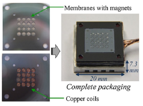
Figure 1 - 4×4 micro-actuator array: mounting and integration into its packaging [2].
CAD Model
The proposed Magnetostatic micro-actuator array features a 4x4 grid of individually controlled actuators with a 2mm resolution. Each unit comprises a mobile PDMS elastomeric membrane atop a Silicon base, centralizing a micromagnet, and a stationary copper coil below the magnet, encircling a ferromagnetic core. Detailed dimensions are provided in Table 1, highlighting the intricate design aimed at enhancing haptic feedback through precise movement and force application.![Figure 2: a). Cross-sectional view of the tactile micro-actuator [1] b) 3D CAD design](/ckfinder/userfiles/images/Cross-sectional-view-of-the-tactile-micro-actuator-%5B1%5D%20b%29-3D-CAD-design.jpg)
Figure 2 - a). Cross-sectional view of the tactile micro-actuator [1] b) 3D CAD design.
Table 1: Components dimensions
| Component | Dimensions (mm) | ||||
| Coil | Inner diameter | Outer diameter | Height | ||
| 0.5 | 1.2 | 1.8 | |||
| PDMS membrane | Length | height | Width | ||
| 2 | 2 | 0.8 | |||
| Substrate | Outer part | Length | Height | Width | |
| 2 | 2 | 0.8 | |||
| Inner part | Inner Diameter | Outer diameter | Thickness | ||
| 1.2 | 1.7 | 0.8 | |||
| Magnet | Diameter | Height | |||
| 1 | 0.5 | ||||
| Core | Diameter | Height | |||
| 0.5 | 1.8 | ||||
| Gap between coil and magnet | 0.4 | ||||
Simulation setup
The study's primary objective is to calculate and illustrate the deflection of the PDMS membrane resulting from magnetic forces during Coil-Magnet interaction, utilizing FEM simulation. This involves coupling EMS's magnetostatic module with structural analysis, following a defined setup sequence for the simulation.
1. Select the appropriate materials
| Part | Material | Density (Kg/$$ m^3 $$) | Magnetic permeability | Electrical conductivity (S/m) | Elastic Modulus (Pa) | Poisson’s ratio | Magnetization Coercivity (A/m) Remanence (T) |
| Coil | Copper (Cu) | 8900 | 0.99 | 5.7 E+07 | Not required | Not required | |
| Membrane | PDMS | 1030 | 1.38 | 0 | 2E+6 | 0.49 | |
| Substrate | Silicon (Si) | 2329 | 1 | 0 | 159E+9 | 0.27 | |
| Core | Permalloy (NiFe) | Not required | 82000 | 0 | Not required | ||
| Magnet | Neodymium-Iron-Boron (NdFeB) | 1.175 | 0 | 954929 1.4 | |||
2. Electromagnetic Inputs
The inductor coil is characterized as a wound coil, with its specifications outlined in Table 3.
| Number of turns | Wire diameter (mm). | RMS current amplitude (A) | |
| Wound coil-1 | 48 | 0.15 | 0.8 |
3. Mechanical boundary conditions
Fixed boundary conditions are enforced on all four lateral sides of the PDMS membrane, as depicted in Figure 3.
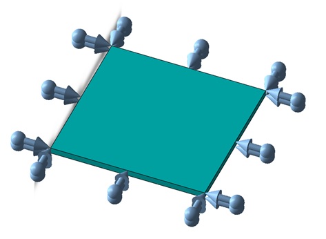
Figure 3: Applied mechanical boundary conditions.
Meshing
To ensure precise magnetic force calculation and adequate elements for stress and deformation analysis, the mesh of the deformed part (elastomeric membrane) requires refinement. The figure below illustrates the entire meshed model, highlighting the application of fine mesh control to the upper sections.
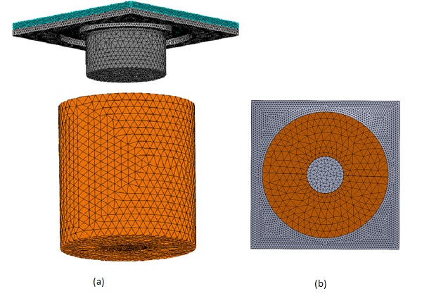
Figure 4 - a). The whole meshed model b). Bottom View.
Results
A multi-physics simulation conducted with the EMS tool enabled the assessment of the magnetic force arising from the coil and magnet interaction. The findings are presented in the figures that follow, with Figure 5 specifically illustrating the magnetic flux distribution within both the core and magnet.
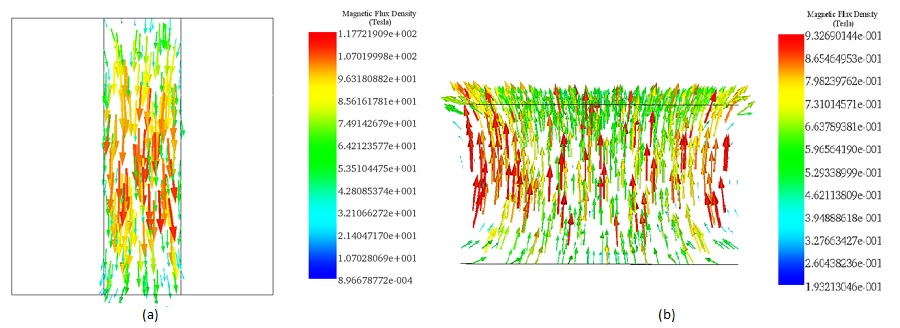
Figure 5 - Magnetic flux distribution across a). the core and b). the magnet parts.
Table 4: EMS Results table of the virtual work defining the coil-magnet interaction.
| Fx-axis (N) | Fy-axis (N) | Fz-axis (N) | |
| Virtual Work - 1 | 2.7957e-005 | 7.9450e-005 | 5.1816e-003 |
The comparison between Reference [1] and the EMS simulation results demonstrates a strong correlation, particularly in the measurements of magnetic actuation force and the maximum deflection of the PDMS membrane. This alignment is detailed in Table 5.
Table 5: Comparative table between EMS and Reference [1] results.
| Results | EMS | Reference [1] |
| Actuation force (mN) | 5.18 | 5 |
| Maximum deflection (µm) | 108.9 | 108.6 |
Affected by the magnetic forces, the membrane bends towards its center, exhibiting considerable deflection, as depicted in Figure 6.
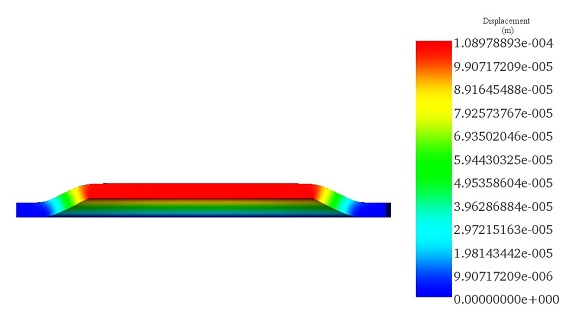
Figure 6 - Section plot of the resultant displacement of the membrane.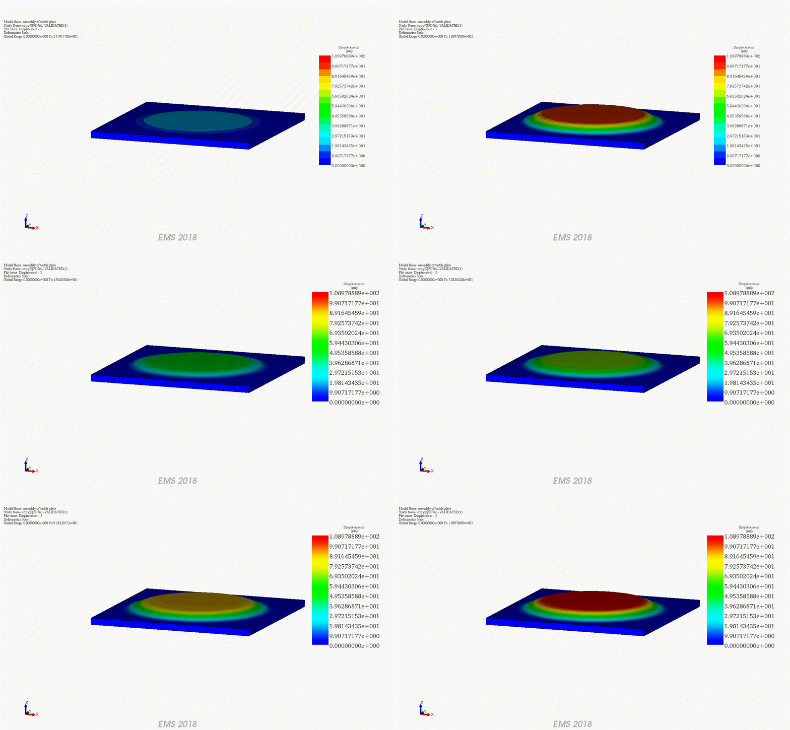
Conclusion
In conclusion, this application note delves into the realm of tactile micro-actuators within Micro-magneto-mechanical systems (MMMS), emphasizing the utilization of advanced materials and micro-engineering techniques. The focus lies on a novel V-beam actuator design, featuring a durable elastomeric membrane atop a Silicon base, integrated with pulse-driven magnetostatic micro-actuators. Through comprehensive simulations and analyses, the study demonstrates the actuator's capability to induce substantial deflections under magnetic forces while maintaining structural integrity. Results unveil precise deflection patterns and magnetic flux distributions, corroborating with experimental data from previous studies. Notably, the membrane exhibits significant deflection towards its center, showcasing the actuator's potential for tactile feedback applications. Comparative analysis between simulation and reference data highlights the accuracy of the electro-thermal simulations in capturing the actuator's behavior. Overall, this study contributes to the advancement of tactile display technologies, providing insights into the design and performance of MMMS-based tactile micro-actuators for enhanced haptic experiences.
References
[1].Streque, Jeremy, et al. "New magnetic microactuator design based on PDMS elastomer and MEMS technologies for tactile display." IEEE Transactions on Haptics 3.2 (2010): 88-97.
[2]. Streque, J., et al. "Pulse-driven magnetostatic micro-actuator array based on ultrasoft elastomeric membranes for active surface applications." Journal of Micromechanics and Microengineering 22.9 (2012): 095020.


